1/4 nazi to pull gulfstream windows

Gear On a 50 or a 900?
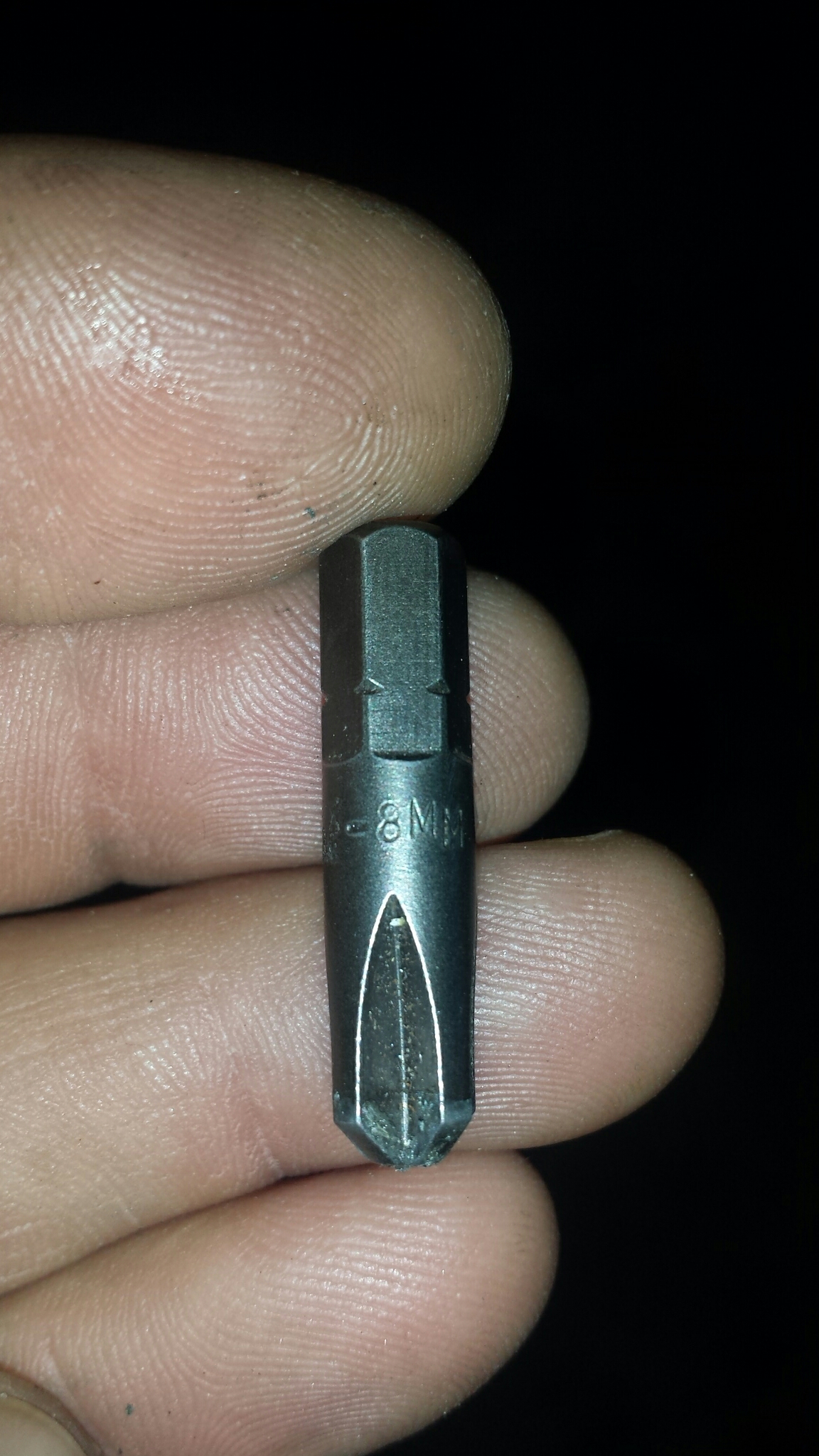

BNEA-8MM APEX
Super duper Apex extractor
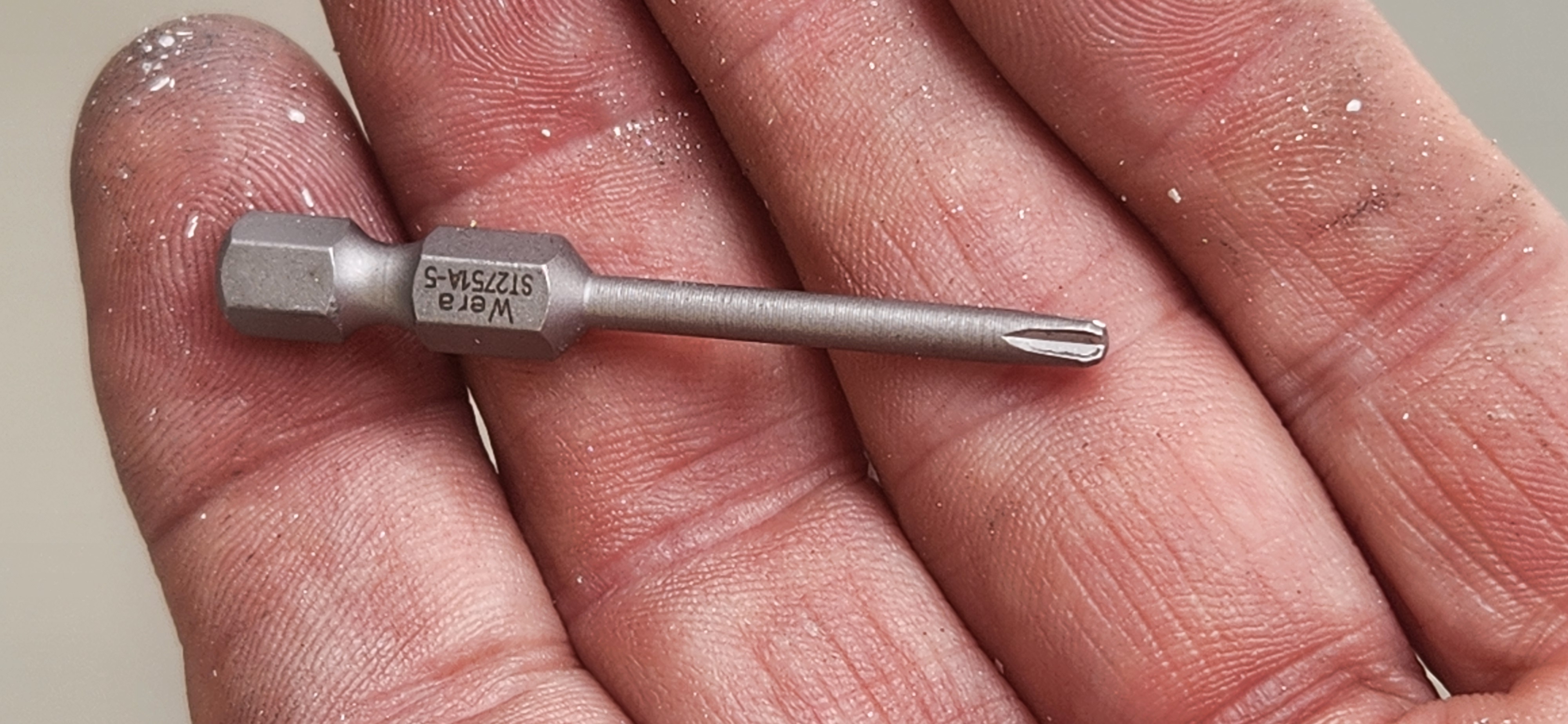
1/4 nazi to pull gulfstream windows
Gear On a 50 or a 900?
BNEA-8MM APEX
Super duper Apex extractor
Slide door
ice door
sun shade
ITEM 31 pilot headset intermit. On to T.o. roll only. Phone audio only…..verified. jack is loose, crackles when moved.. NOTED THAT THE FACTORY ORIGINAL PHONE JACKS ARE STEREO. NOTED UNUSED 2ND CHANNEL WOULD SHORT TIP TO BARRELL. REMOVED 2ND AUDIO CHANNEL ELECTRIC AL CONTACT from all 3 JACKS. RESTORED HEAT SHRINK INSULATION. OPS TESTED AUDIO SYSTEM IAW AMM
Aft left card table trim outboard.
2 brass nameplates missing at r. Mid bulkhead.
Aft divan aft phone jack no left channel audio. Several 1/8th Jacks loose , tighten and recheck . Fwd rh. Vip. Phone audio inop.
Toilet will not take blue juice after flight.
Lock stripe indicator
Pressurizioon
Yoke clips off.
Check all books revisions.
ITEM 44. Left amp switch. REMOVED FAILED LEFT AMP METER SELECTOR SWITCH P/N K615-0-0. INSTALLED NEW SWITCH P/N K615-0-0. OPS TESTED SYSTEM IAW AMM 24-31-00-720-801. perform final test at the end
#2 Gen residual 1.96
#3 1.82
#2 ai amber functions cotrectly. No test
Left ob slat dentdeath
Front carpet curls up….double stick tape.
Ann outboard of copilot pfd inop….bulbs.
Isle light at toilet floor comes on and off when you tap on it.
Upper rh 2.00 o’clock Radome latch broken. Will not bump latch outward.
Egpws data base 455. Label small black pushbutton as EGPWS TEST.
Leaks at aoa screwes. Rad alt ant.
RH RTU plastic bezel cracked.
Velcro at smoke goggles
left sun visor bent out. Strikes dv window frame .
Item 49….pilot I head panel dark at lower switch row, upper left volt meter. Both oh dimmer control panel legends dark. ACCESSED OVERHEAD PANEL. REMOVED 9 FAILED BULBS. INSTALLED 9 NEW BULBS P/N 6838. REINSTALLED PANEL. OPS TESTED IA ARM 33-10-710-802.
Left valance upper cover fwd edge and aft end velcro does not stick.
RH reversion REV control face paint crackley
1R seat back loose on the hydrolock.
4L hydrolock lateral does not release easily. You have to squeeze the lever to max travel to get inboard.outboard. translation.
1L drink rail structure below veneer broken. Veneer does not sit flat.
MED FRONT UPPER ROLLER BRACKEN GOUGED.
################
RH OUTBOARD AIR BRAKE FAILS MILLIOHM CHECK. REMOVE BONDING BRAND AND CLEAN.
LEFT OUTBOARD SLAT BRONZE, LEFT. OUTBOARD FLAP BRONZE, LEFT INBOARD FLAP BRONZE, RH OUTBOARD FLAP BRONZE FAIL MILLIOHM CHECK.
RH STROBE BULB BLACK, DEFORMED.?
LH STABILIZER ONE WICK FAILS MEG OHMARCH TEST.
ELEVATOR AUTOPILOT SERVO MOTOR CABLE TEST SLIGHTLY HIGH. ASK PILOTS ABOUT AUTO PILOT ALTITUDE HOLD PERFORMANCE.
LMLG MANUAL DROP ROLLER PEENED. REMOVE ARM AND EVALUATE.
NOTED SEALAND RAMPS AT RH NLG BOX STRUCTURE RELEASED, SURFACE OF PRC CRACKED , POROUS. REMOVE SMALL PORTION OF PRC ANDROID INSPECT FOR HIDDEN CORROSION. pictures avalable.
Noted wire harnesses adjacent to sb 530 compliance area could chafe same structure. Remove avionics at glare shield and tie-wrap harnesses correctly. Pictures
COMPLIED WI RH MANDITORY SB 530, INSTALLATION OF PRO TECTION PLATES UNDER THE GLARESHIELD.
###############
Final close up memory items.
recheck CVR area mic after glares held install.
touchup light spill at overhead panel.
redo 24-31-00-720-801 to check LH Gen amp sw
Final seal prc all three gear.
Check 3 shock strut pressure
Lube all 3 gear
Pilot adc pn 822 1036 467 sn 2931
Copilot sn 2865
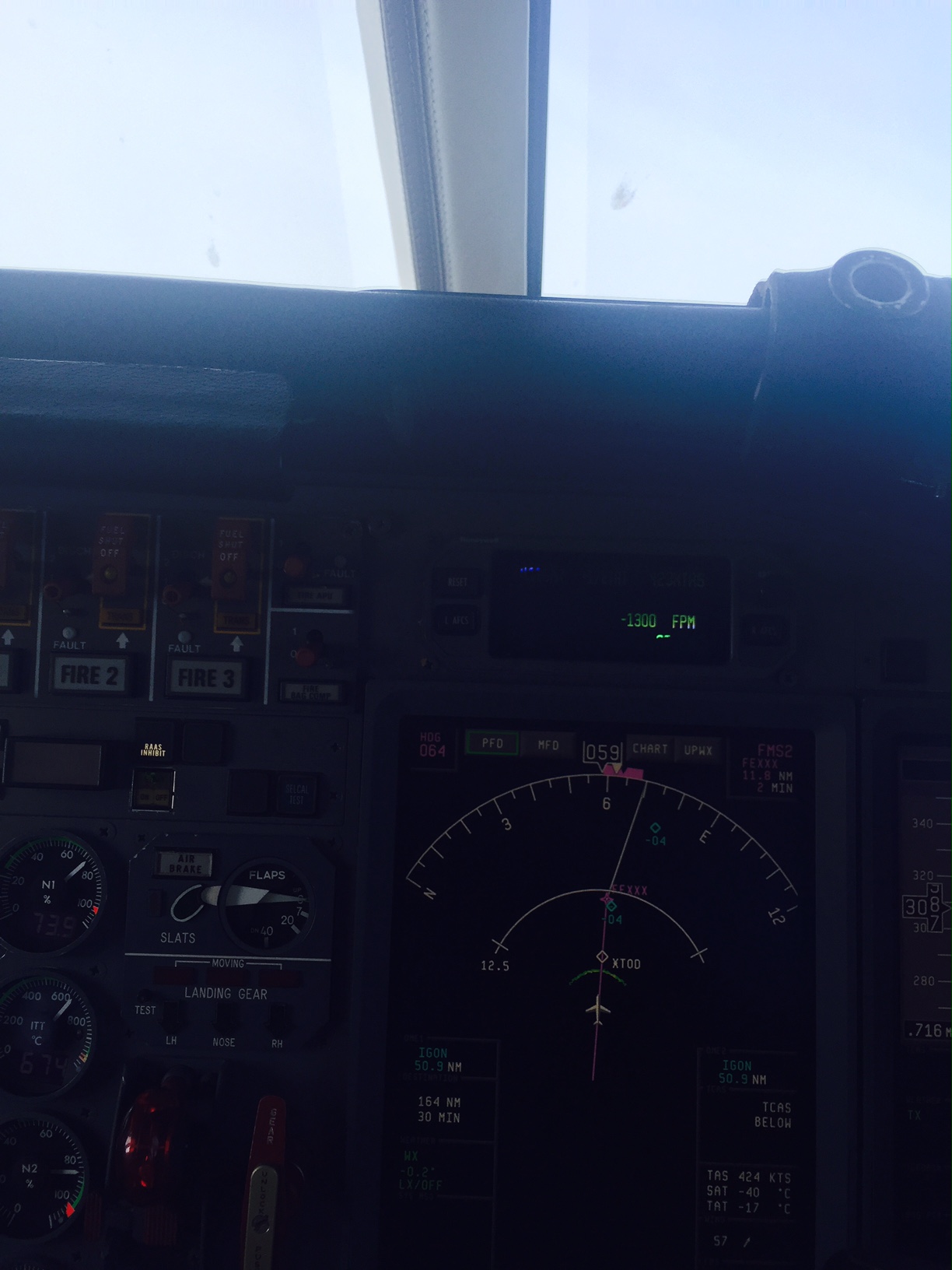
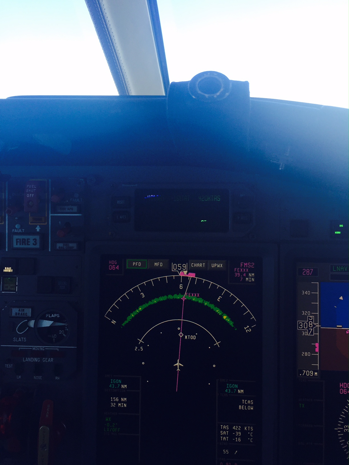
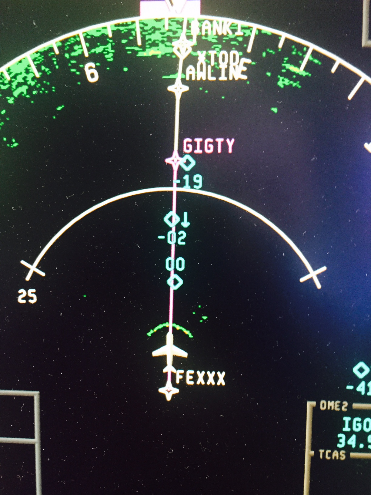
Apparently, i am the last avionics technician on the face of the earth that did not know what “Altitude Rings” are.
Here is the Honeywell training Blah Blah :
Altitude rings Its a PPT
Altitude rings Or here for a PDF.
It is a arc shaped return that results from the radar bouncing off of the top of the radome when the tilt is all the way up.
WHO KNEW?
How do you explain the difference between LAFCS-RAFCS and COUPLED LEFT, COUPLED RIGHT?
======================================================
Here is a few pointers on ENGAGE logic from a Honeywell quick troubleshooting guide (my comments in red):
SPZ-8000 Autopilot Engage Logic
What is needed to satisfy the engage mode:
Stall warning not active (2 on the 900)
TCS P/B not pushed
YD Quick-disconnect P/B not pushed
AP Quick-disconnect P/B not pushed
Go-around P/B not pushed
Manual Trim not active (Also, Emergency trrim in the pedistal on the 900)
DADC valid
AHRS valid
Ground Engage Inhibit not active (no WOW engage allowed on the 900)
Servo Power Valid
What takes place when the A/P is engaged:
The FZ-800 is allowed to control the servos.
What components are part of the engage command:
TCS P/B
YD Quick-disconnect P/B
AP Quick-disconnect P/B
Go-around P/B
Manual Trim P/B
DADC
AHRS
WOW
What is need to satisfy the disengage mode:
To have any of the engage signals change state.
What takes place when the A/P is disengaged:
The FZ-800 is not allowed to control the servos.
What components are part of the disengage command:
Same as engage.
It takes extra long to load the first chart after a data load.
If you see this it’s a bad data load

20HW is the Oheat warn box.
Unplug the B connector. you should get a solid BLEED OHEAT light, and a dark ECU OHEAT light that will not test.
unplug 12hw2(?) at #2 engine firewall, should be flashing OHEAT light.
………………………
Please see the attached CMM to test the RP129-02 sensors. I have also attached the FSA 36-00-008-R03-A in regards to the improved RP482-00 or RP482-01 sensors.
Regards,Camron Madsen
Resistances for the temp sensors. you can test these from teh aft compartment without having to remove them.:
Shortest description of the current squawk:
WR 880 on F900 087 has a range band on which no target is painted. No ground return . No weather return.
Where we stand presently:
We have proven that one of the exchange radomes was bad. We suspect that ONE of the exchange radar pedestals was bad because the previous squawk was NFF and our squawk was identical to the previous user’s squawk.
There are 3 possibilities:
1 . Honeywell has provided 2 bad exchange radars in a row AND we have misinterpreted a good loaner as failed.
2. Dassault/Duncan/Aerostructures/ has provided/painted 2 bad Radomes in a row.
3. There is some other failure mode that we are simply not bright enough to figure out. (as per Honeywell enginneer, P-Static and so forth)
=============================================================
Story starts like this:
SPRING 2013
We had a small lightening strike on the radome
which necessitated the removal of the entire NOSE of the aircraft, not just the radome…..nice.
After a MONUMENTAL hassle, and $7000.00 worth of shipping, we got a Falcon exchange radome/nosecone installed on the airplane.
July 2013 was the install date of the first exchange radome.
It came materhorn white and flown that way for ~3 months. No radar problems. (?) (ask Abe) (review work orders) We flew the airplane to Lincoln (DATE?) (Need Duncan Work Order for radome stripes) and had it paint striped.
After a MONUMENTAL hassle and ~100K of unrelated work….Ahem….. we got the airplane back. The crew related various radar problems that were not definite……. just hard to pin down.
this email, 1/16/14 seems to be the first indication of ghosting on the radar
1/16/14
Ron
Could you send me a email that details the ghost returns.
We will probably sent the radome to Applied Aerodynamics in Dallas to have it tested.
They have requested a pilot report of where the ghost returns were most prominant. For example most ghosting occurs on pilots side or copilot side.
Also could you detail the part about the ghosting having started after the paint restripe.
We put a exchange radar RT on the airplane.
Install Radar S/N 1010B446 (Check install date)
Problems persisted.
~ Jan 2014.
while the airplane was at FTW for other work (Zcheck?) We sent the radome for transitivity tests. It failed massively. Like 60% clear over half of the radome.
Vendor. AppliedAerodynamics (www.aerodyn.com for address)
Contact mr. Campbell W.o. 487 item 57.
Please evaluate moisture and transmissivity of radome/nosecone Dassault p/n fgfb208b1 SN BZ160.
PO31469 Page 9 shows Radome S/N BZ160 failed, Class F radome with areas ranging from 51% clear to 70% clear. The rest is for the restripe of Radome S/N BZ165
~1 Jan 2014
We had a second exchange radome delivered to (Duncan?) (AppliedAerodynamics?) and Paint Striped. We sent a driver to Lincoln to pick it up. Spring 2014.
Later , Falcon jet would claim that the S/N BZ160 radome was not defective:
RadomeBZ160TeardownStGobain. I simply do not believe that. St Gobain sanded and repaired, and THEN evaluated the radome. The Teardown notes multiple layers of paint on the radome.
This is where a new(?) and DEFINITE radar problem showed up. A dead band with no return 10 to 50 miles off the nose of the airplane. (????ask Abe abouth the 10 to 50 mile numbers??????)
From Abe:
Gerry.
The unit seems to have no return in the band near the bottom of the screen.
The radar is nearly blind to weather at short ranges.
Abe exaggerated it by full down tilt and max gain.
The installed radar is a ………wait for it………. no fault found unit.
P.o. shortly.
Todd
~July, 2014
Install Radar S/N 04105183
TLP0589 for exact date.
Max gain tilt down shows the problem at its worst:
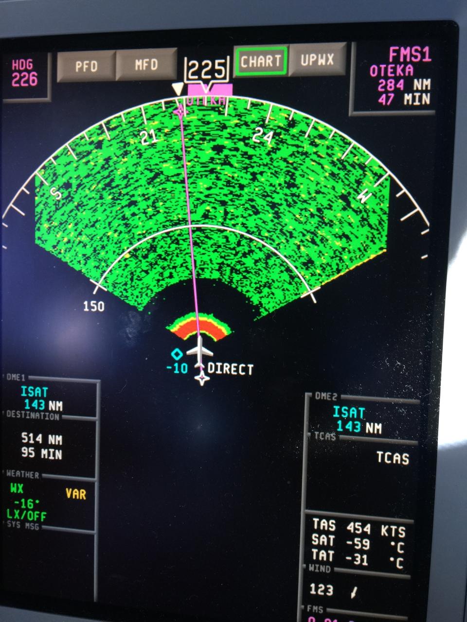
We installed a radar P/ N 7021450-801 S /N 04105183 (Need TLP for Date)
after some time, the same problem occurred. After review of the previous tear down report
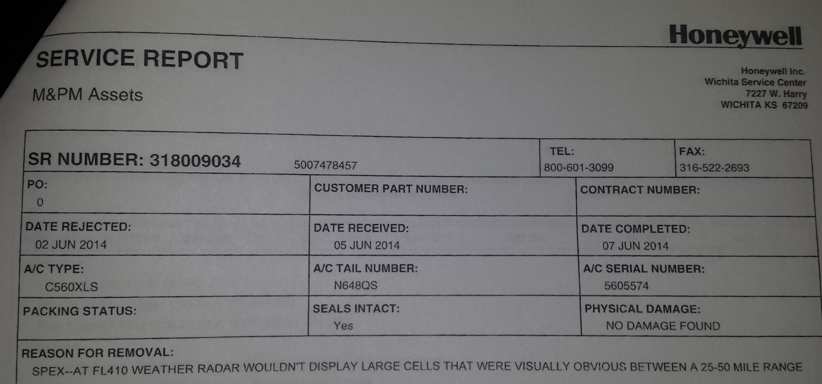
PO31724 (1) Shows previous squawk. This is for S/N 1010B446, P.O. was issued June 5 2014
The exchange unit had previously been squawked with the EXACT same squawk on a Cessna 560. Honeywell tested, No Fault Found. This was obviously a DOA exchange.
Feb 20, 2015 support trip to San Antonio.
REMOVED FAILED RADAR RT P/ N. 7021450-801 S /N. 04105183 (NO RETURN AT SHORT RANGES) . INSTALLED REPAIRED RADAR RT P/N 7021450 S/N 99021268.
BZZ radar install 1268 installed 19 FEB 2015, W.O. 0636 item 5
this appeared to not affect the problem at all. Ron Burks sent along a sent of pictures of a very similar problem as the previous radar:
Gentleman,
I hope this email finds you well.
Please see attached pictures that I took during yesterday’s flight.
On the pictures you can appreciate that we were on IMC and the radar was not showing anything for the for the first 7 miles ahead of us.
On the second picture you can see a return arc at approximately 7 miles too.
I hope you find this information useful.
Best regards to everybody.
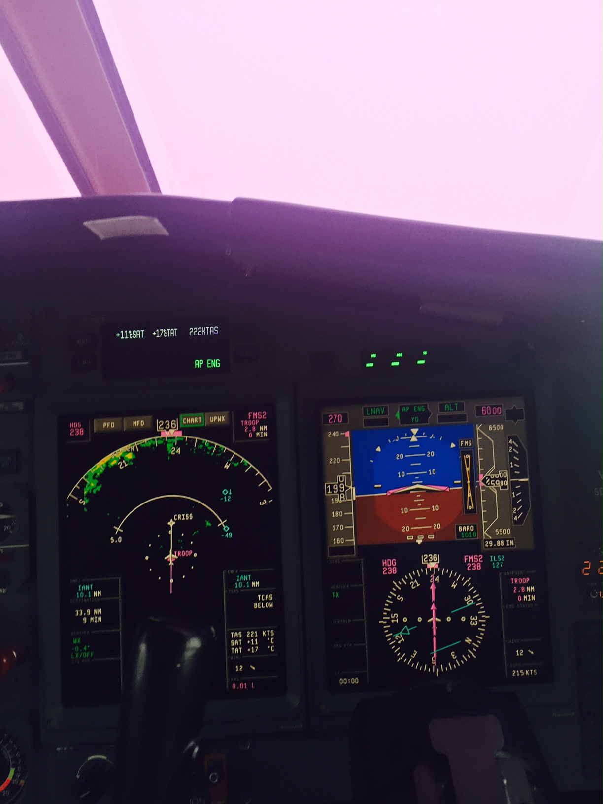
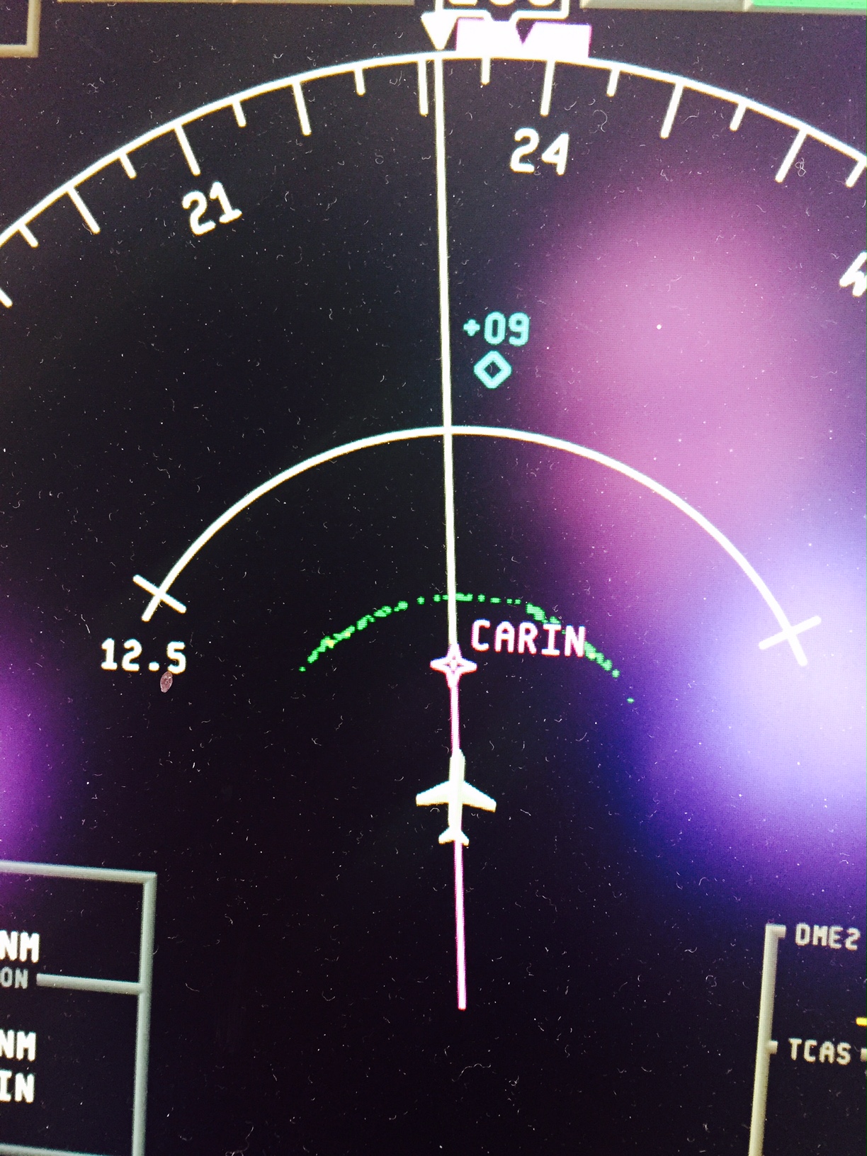
we suspected the installed unit was ANOTHER bad Honeywell exchange radar RT. This time we elected to test fly the airplane with a known good radar from F900 S/N 051. San Antonio to KFTW.
The loaner radar from a VP-BMB acted exactly the same, even though there was no weather KSAT to KFTW to verfify the complaint. The ground return was the same. No return at all at short ranges.
here is the video from Craig’s phone
http://youtu.be/-UOudrY2dw8 failed behavior(?)
We ran the loaner radar 038287 on KFTW pointed south to Fort worth…..returns are normal on the ground for both radar pedestals.
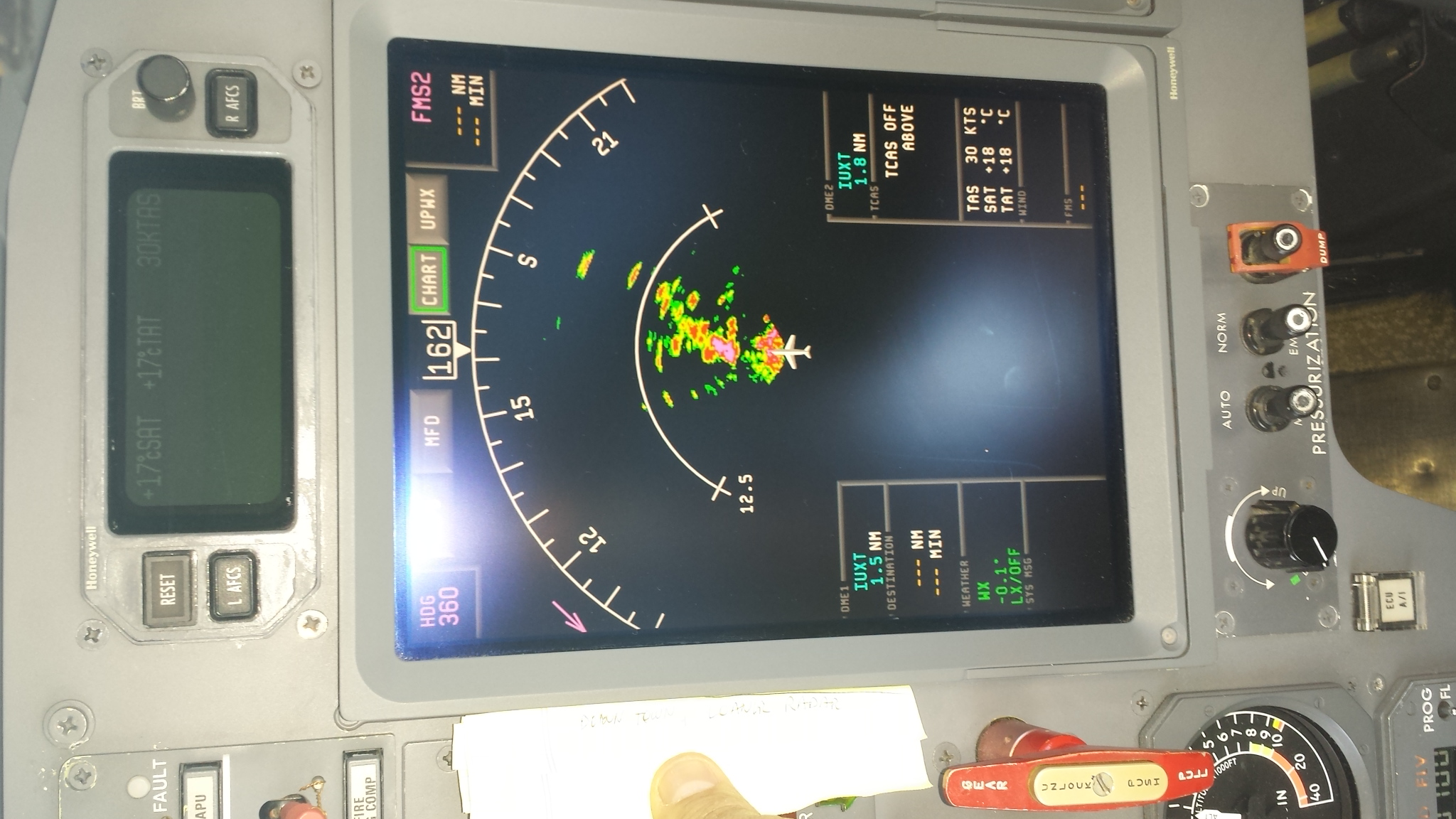
And then swapped back to radar sn 1268 the BZZ radar in the same conditions. Almost exactly the same conditons. The radar return is almost exactly the same.
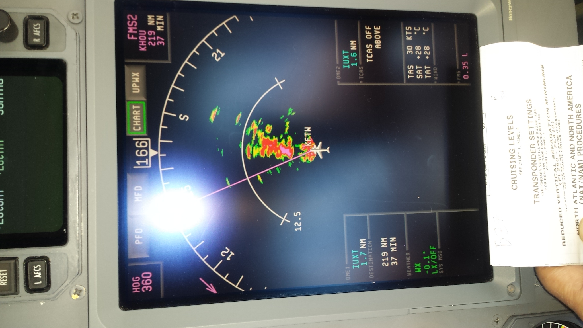
27 Mar 2015, the radar and the loaner radar is confirmed good on the ground, and bad in the air.
Here is the info for the 232 port troubleshooting
The terminal setup to communicate with the PRIMUS 880/660/440 is as follows:
Baud rate 9600
Com settings No parity, 8 data bits, 1 stop bit
Terminal family VT/ANSI
Default terminal Emulation ANSI
Default download Protocol ASCII
Echo OFF
Page 345 gives the Radar Plate Size strapping
*880 manual deleted*
Duncan install prints showing test port:
BZZ_Radar_Prints_100104022 Rev A Primus 880 Weather Radar
The airplane left KFTW for KSAT with the original sn99021268 installed.
Case number CASE-10620295 [ ref:_00D30dWxY._5001
John
Honeywell sent us the same radar we sent them with the corret previous write-up, but the wrong previous airplane…….. we rejected the unit because it is the previously suspected unit.
We rejected tis exhange unit because it is the same old unit, this will not advance our troubleshooting.
Mar 31 2015, rejected a honeywell exchange radar for these reasons:
Honeywell exchange rejected, S/N 041055183 fedex 806782588115
April 1 2015 pictures, BZZ radar S/N ______ reinstalled.
This Service Report make absolutely no sense It has Craig’s squawk write-up, but it says it was removed from a GIV
the third one is a Altitude ring
tl:dr;
The Radio Altimeter Aux output was only operational between .4v and 3 v or so. This made the ground prox see the Radio Altitude as 348 feet at all times. This subtle failure was missed three times on the bench.
Cl 601 …A
RESOLUTION:
A loaner Rad Alt box fixed the EGPWS call out problem.
Here is the video of the EGPWS working properly
Squawk: EGPWS gives “Pull Up” “Terrain” in flight
Supporting facts about squawk:
1. Fault occurs during clmb, or first level off, AFTER 2000 to 3000 feet.
2. Associated “Pull Up” “Terrain” on ground was fixed by properly setting zero.
3. The number 1 and number 2 IRU’s have been swapped just in case the problem was IRUAlt.(??2 IRU inputs?)
Details about EGPWS
> ps
EGPWC CONFIGURATION:
PART NUMBER: 965-0976-003-214-214
MOD STATUS: 10
SERIAL NUMBER: 17306APPLICATION S/W VERSION: 214.2
CONFIGURATION S/W VERSION: 214.11
TERRAIN DATABASE VERSION: 473
ENVELOPE MOD DATABASE VERSION: B07
BOOT CODE VERSION: B101.2CURRENT FAULTS:
GPWS COMPUTER OK
GPWS EXTERNAL FAULTS:
IRS BUS INACTIVE
EFIS BUS INACTIVE
FMC BUS INACTIVE———-
Envelope Modulation INOP
Terrain Clearance Floor – Position ErrorPROGRAM PIN CONFIGURATION:
Aircraft Type = 85
Audio Menu = 0
Altitude Callout Menu = 15
Configuration Option 2 Selected
Smart Callout Selected
Optional Inputs Selected
Dual GPS Selected
Windshear Caution with Voice Selected
Bank Angle Selected
Peaks Enabled
Mode 6 Low Volume Selected
Terrain Awareness and TCF Disabled
Obstacle Awareness EnabledRAW PROGRAM PIN STATES:
Program Pin 1 (TP-10A) = 6 (TP-12C)
Program Pin 2 (TP-10B) = 3 (MP-15D)
Program Pin 3 (TP-10C) = 2 (MP-03A or Gnd)
Program Pin 4 (MP-04D) = 8 (TP-04D)
Program Pin 5 (MP-04B) = 2 (MP-03A or Gnd)
Program Pin 6 (MP-08A) = 5 (MP-07B)
Program Pin 7 (MP-14D) = 6 (TP-12C)
Program Pin 8 (MP-05A) = 1 (Open)
Program Pin 9 (MP-02C) = 1 (Open)
Program Pin 10 (MP-04A) = 1 (Open)
Program Pin 11 (MP-04C) = 1 (Open)
Program Pin 12 (TP-05B) = 4 (MP-03D)
Program Pin 13 (MP-05B) = 3 (MP-15D)
Program Pin 14 (TP-02C) = 2 (MP-03A or Gnd)
Program Pin 15 (MP-15C) = 1 (Open)
Program Pin 16 (MP-08B) = 5 (MP-07B)
Program Pin 17 (TP-06D) = 1 (Open)
Program Pin 18 (MP-15A) = 1 (Open)
Program Pin 19 (MP-15B) = 1 (Open)
Initial Pilot video of squawk:
http://youtu.be/dm5NXfQ25Co, Video shows Baro ASL 3000 – level. The Rad Alt shows 2200 feet to 2350 feet, makes sense around the DFW area, ground level is 750 feet or so.
RadAlt RT300 has been to Lincoln “3 times”.
P/N S/N
Apr_30_2015_8130 (1) replace Downconverter
May_16_2014_8130 (2) Capacitors
June_25_2015_8130 Resistor, connector
EGPWS has been to Honeywell,
Egpws work report work report. No Fault found.
Deeper troubleshooting at RadAlt input:
Duncan has rung out Rad Alt Aux wires.
Chuck at AAT put a volt meter on the EGPWS 13A and 13B:
0Feet = .367 volts DC. 100 foot test = ~2.36 VDC,
EGPWS Air Inc 552 voltages and wires
Video http://youtu.be/tNAsbRlpKNk
Ground troubleshooting in WinViews:
Ground test FAULTS
> FHW
WARNING HISTORY:FLIGHT LEG 1:
TCF TooLowTerrain ( 4771:58:39)
TCF TooLowTerrain ( 4772: 1:13)
TCF TooLowTerrain ( 4772: 4: 4)
M3 Don’tSink (Pause) Don’tSink ( 4772: 4: 8)
M1 Sinkrate ( 4772: 4:27)FLIGHT LEG 2:
M3 Don’tSink (Pause) Don’tSink ( 4771: 6:35)
M3 Don’tSink (Pause) Don’tSink ( 4771: 6:46)
M3 Don’tSink (Pause) Don’tSink ( 4771:26: 5)
M3 Don’tSink (Pause) Don’tSink ( 4771:27:44)
M3 Don’tSink (Pause) Don’tSink ( 4771:27:46)…….and so forth
(Use CXR RawARA1)
0 Feet = -1.3 to -2.0 feet (Parameter RawARA1)
100 foot test = 98.7 feet
> cxr RawARA1
RawARA1 97.557308 Cstm=0x00000167 Flg=0x00000000 T.Upd=213400
Usr=3 psDEFAULT +VALID
> cxr RawARA1
RawARA1 23.977366 Cstm=0x000000A7 Flg=0x00040000 T.Upd=215290
Usr=3 psDEFAULT FW+VALID
> cxr RawARA1
RawARA1 -2.082198 Cstm=0x00000064 Flg=0x00000000 T.Upd=217200
Usr=3 psDEFAULT +VALID
IN AIR results from WinViews
With Baro reading 3000, EFIS RA reading ~2300 FT……..
RawARA1 is only 354 feet. THATS BAD.
RawIALT1 was about 2900 feet.
WHAT SHOULD THE VOLTAGE BE AT 480 feet AGL:
V = .02*h +20
=10 volts for 480 feet.
WHAT SHOULD THE VOLTAGE BE AT 2500 feet AGL:
According to DAC international Install Manual,
Volts = 10*(1+LN((ALT + 20)/500) so 2500 feet is 26.16 VDC…… correct because 480 feet works out to 10VDC, same as low formula
WRONG……..According to the RT 300 book
Volts = 10* LN((ALT + 20)/500) so 2500 feet is 11.6 VDC .. WRONG
EGPWS works correctly with loaner Rad Alt RT
rad alt delay lines work card
Delay line DataSheet
Balser 817 781 9859
Harold Henderson 818 398 1425
Scott Mckinney at Duncan 402.479.4212
Josh DOM AAT 817 507 8676
Jorje 817 395 3382
Joel 214 714 6289
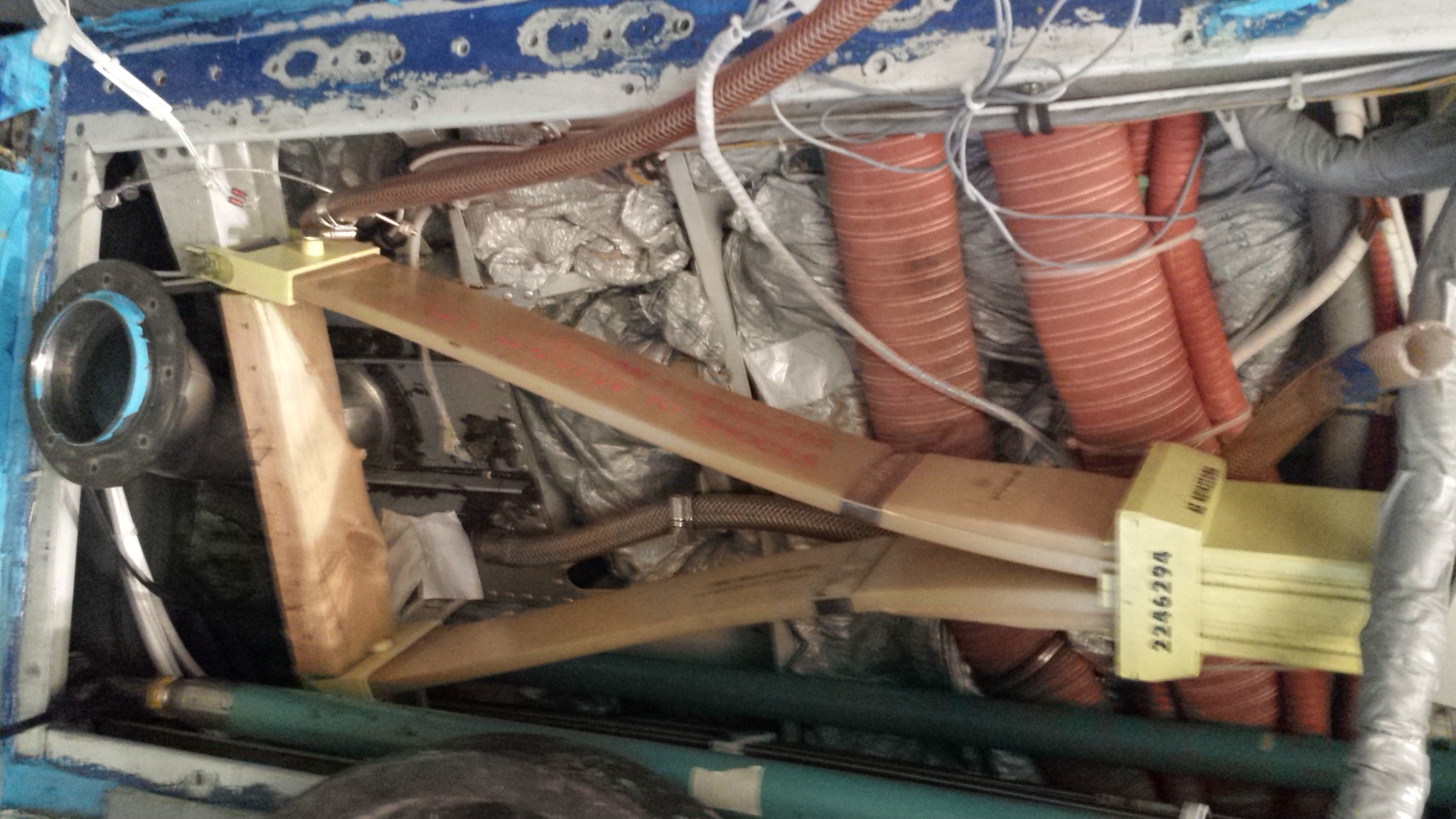
Falcon 900 MED spring
http://www.grainger.com/category/band-clamps/hose-clamps/pneumatics/ecatalog/N-afs