
Vector ink
Vector ink
Cessna quoted 41,000.00 as of June 2026
Long Story:
We are chasing a very elusive noise at the VIP seating area floorboards. Occurs during climb only. Slats clean only. !First flight of the day ONLY!!!!!, with one SLIGHT exception) , 4000 to 10,000 feet altitude (initially). Starts out as a hoot, then drives the floor boards with a drumming rhythm enough to see your legs move.
After installation of a loaner tank press valve, squawk changed to 7500 ft to 20,000 feet. (did we put a bad loaner Tank Press valve in it?)
Never occurs in cruise, never on descent, not related to maneuvering,or wing heat. (Later observation: wing tank depressirization via the GRAVITY REFUEL switch will IMMEDIATLY stop the noise. Hard won knowledge)
Only replicates occasionally.
Sirenage was the obvious first suspect. (We did a full blast replacement of all seals and sirenage strips. The old seals were flat and deformed, so we thought we had it for sure)
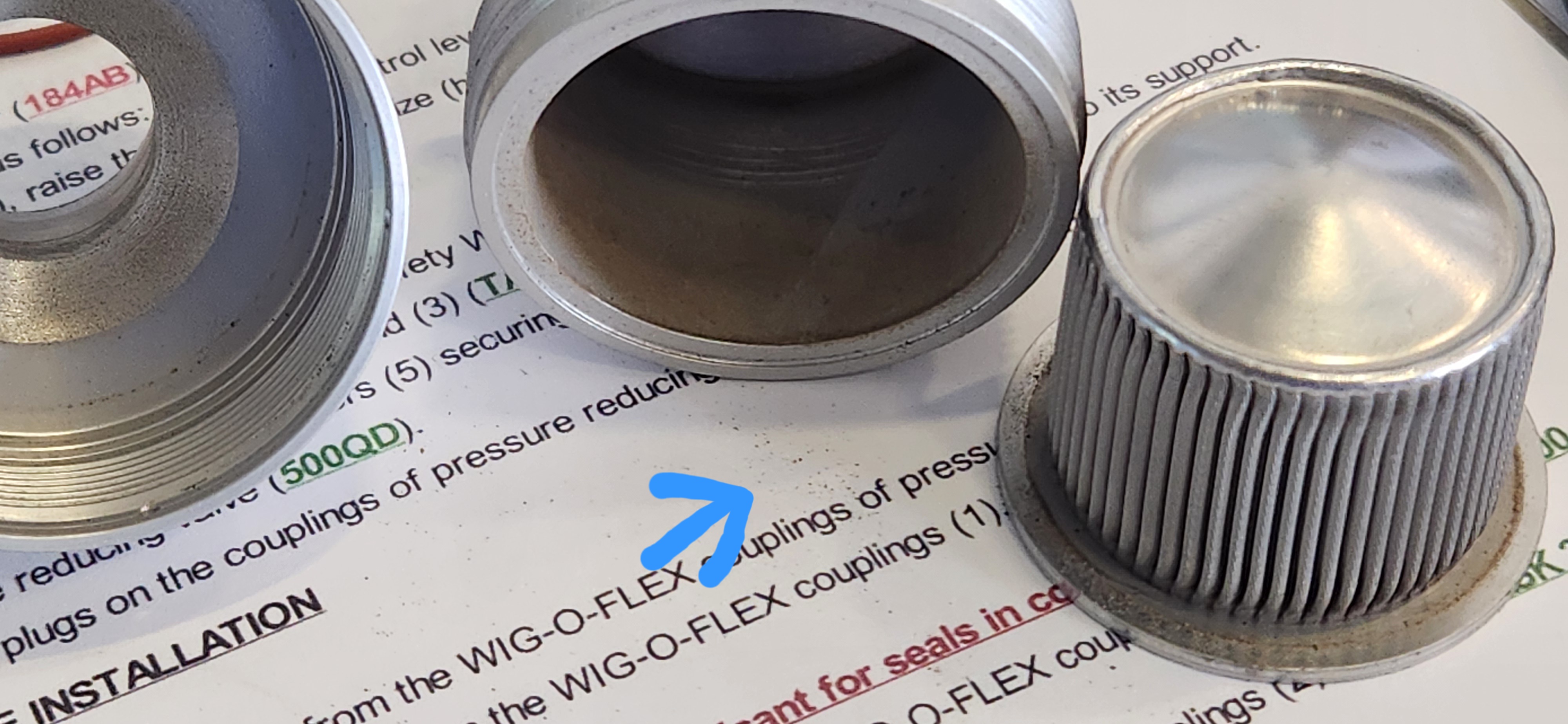
Now, we seem to have confirmation that the Wing Tank Regulating Valve over pressurize enough (3.6 to 3.9) to crack the clapper valves at Frame 25. This drives the (empty) forward tank through the over wing pressurization tube. The Clapper Valves live up to their name…possibly.
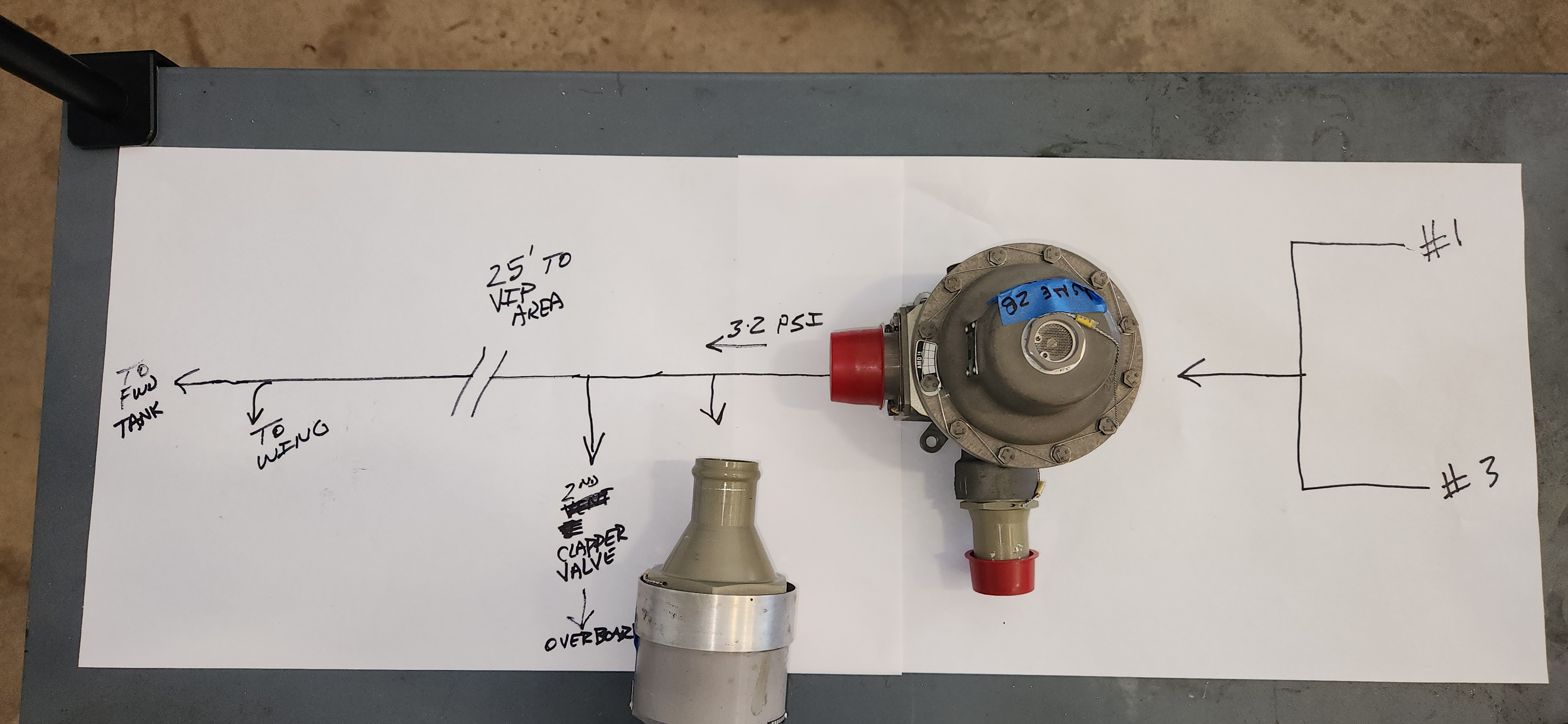
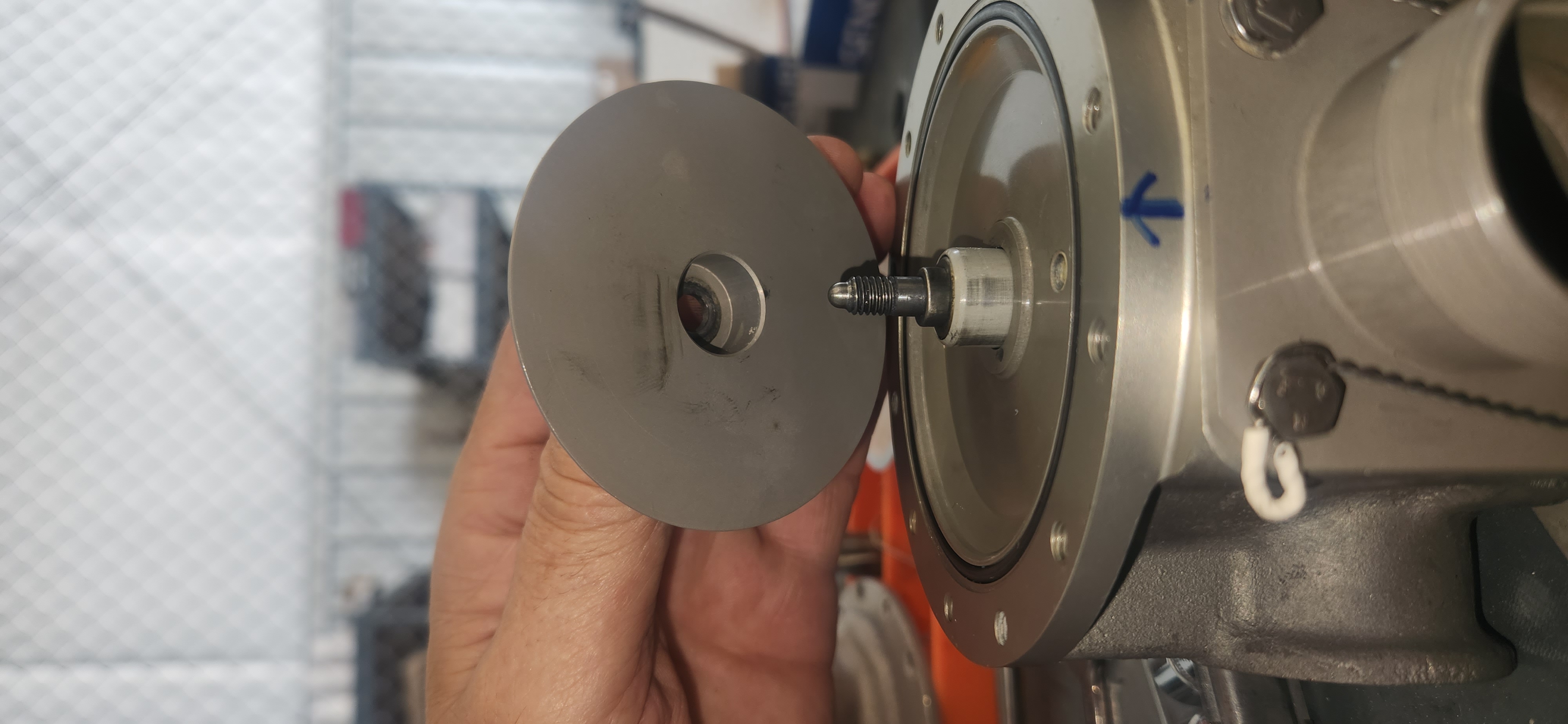
The original valve was later post-mortemed, it has scratches on the center shaft, and white dirt inside.
Take off is at 4:20, max O’press is at 5:20, then the clapper valves obviously crack open. (Upside down, pressure Gage is on the bottom) Goes to about 3.9PSI max, before it starts to shutter.
this was with the loaner valve from another in fleet airplane that was proved to be failed, cracked diaphragm retaining ring
https://youtube.com/shorts/6XJ6TrL20NE?si=gU_Tz4qZDVqGxeif
here is the trimmed down video. the pressure gage(top, white face) runs up o about 4.5, then some thing lets go, the pressure back to about 4, then stays there while the needle shutter.
here is the PDF of the flight profile.
N716BH JUNE 22 TEST FLIGHT flight profile
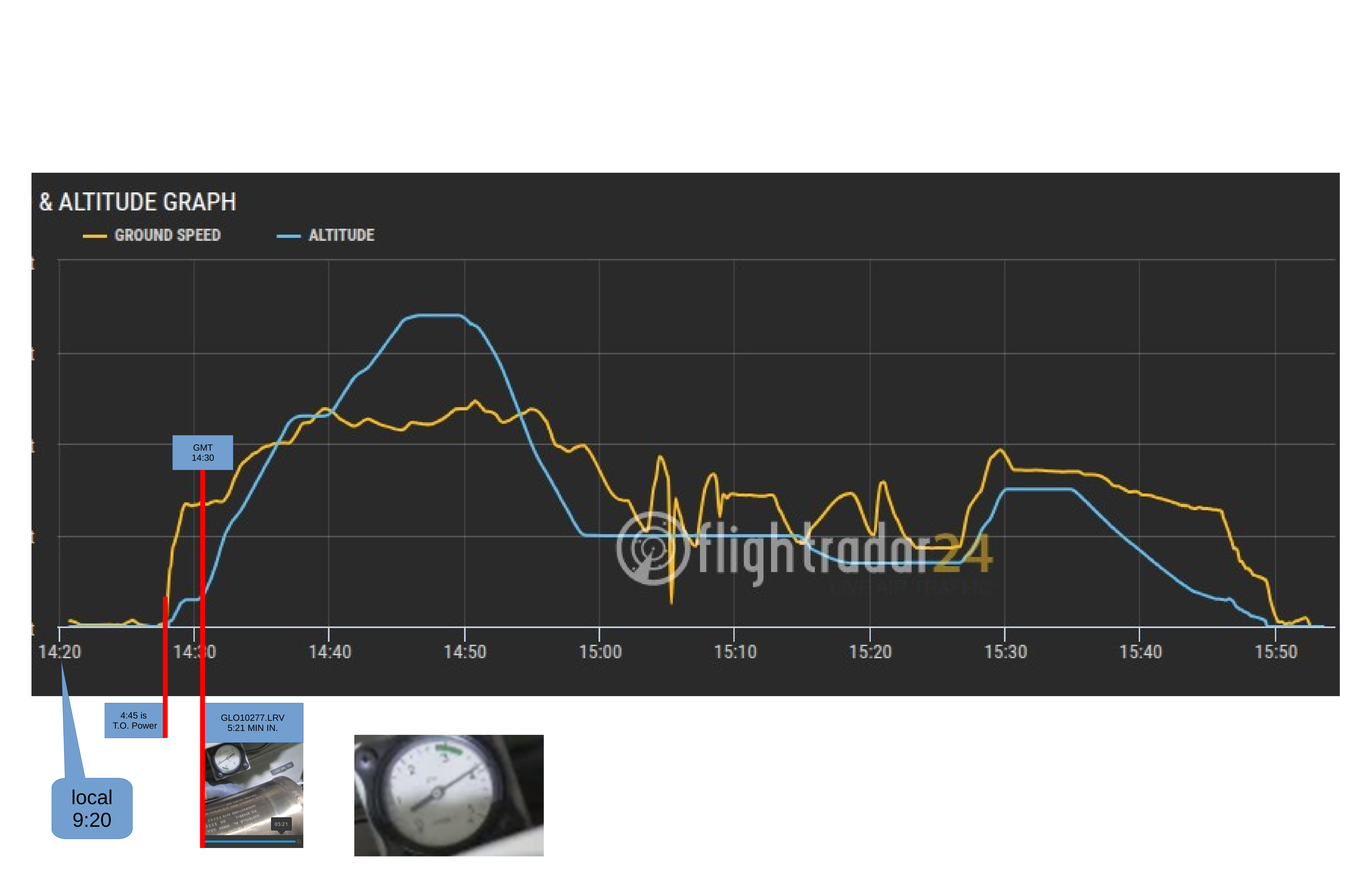
we plumbed in a second Gage at the 1 PSI bib to verify we are not chasing a gage problem (starts around 134)
With a factory new pressure regulating valve, and 1 new Clapper valve, we still witnessed the noise ath the VIP seat area. The noise went away when we vented the tanks using the “Gravity refuel” switch. Then cam back briefly when the tanks pressurized again.
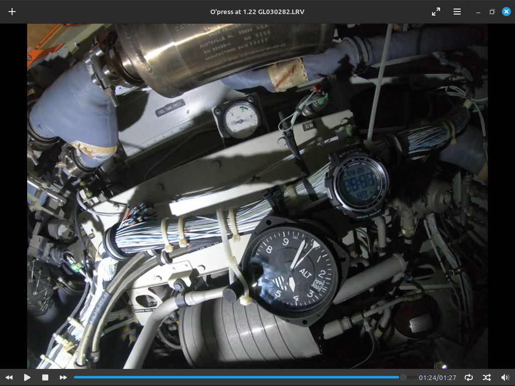
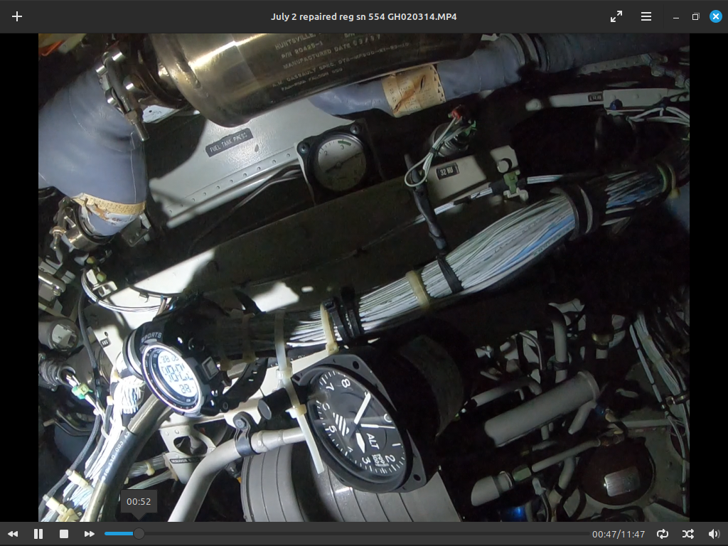
We captured the event on video. Starts at 5500 feet, the over pressure to 4.2, then a sudden decrease to 4.0 and the needle vibrates.
clipped video below, the altimeter( lower, black face) runs through 5500 feet, then the needle lurches down and starts to shutter. That is when we got the clattering noise in the floor board
Happens at 56 seconds into the video
The noise IMMEDIATLY quit when we used “Gravity Fuel” switch to dump the tank pressure.
Once back on the ground, we pressurized it again on the ground and observed a failure.
and the FACTORY NEW valve “ticks” with a corresponding jump on the needle.
New valve sn 2160 verified failed on shop air pressure
https://youtube.com/shorts/QVWC_ZSPRXA
We are now ordering another valve, this time an overhauled regulating valve. We are also ordering the outboard Clapper Valve for good measure.
We can now reproduce something similar to the noise by cramming high pressure shop air into a clapper valve.
We performed the tank leak down as per amm. We are within limits, with the minor leak being the 1 PSI valve.
July 2 troubleshooting with a exchange valve, Midway “Repaired” exchange regulator installed. It over pressurize to 3.6 then shutters for a minute or so.
here is a picture of the valve, already 4 PSI by the time we get to 3000 ft AGL.
here is the long video of the July 2 flight.
Later , on the ground, we can hear the front tank drumming throught the skin of the airframe. https://youtube.com/shorts/05HVUKZIPUE?is=mZT29wfxynAhjpFp
July 3 troubleshooting
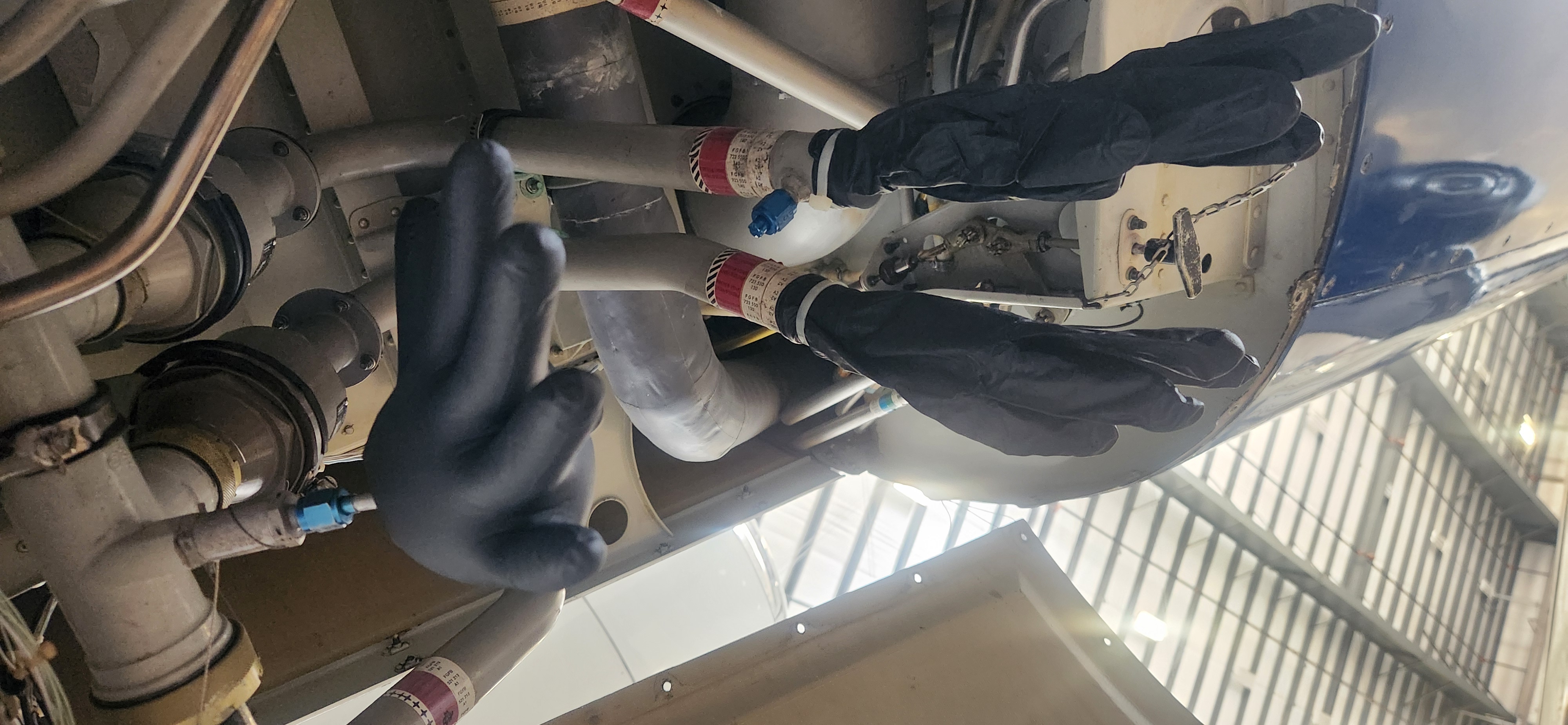
We suspicioned possibly fowled input filter would contaminate any installed reducing valves. Accesed and dissambled. Slight dust on only the number 2 engine filter. Not a factor. Performed check valve reverse flow check.
*****NOTE****** this is the OTHER in-fleet airplane, not the problem airctaft. We just flew this one with a camera to get normal inflight performance data points.
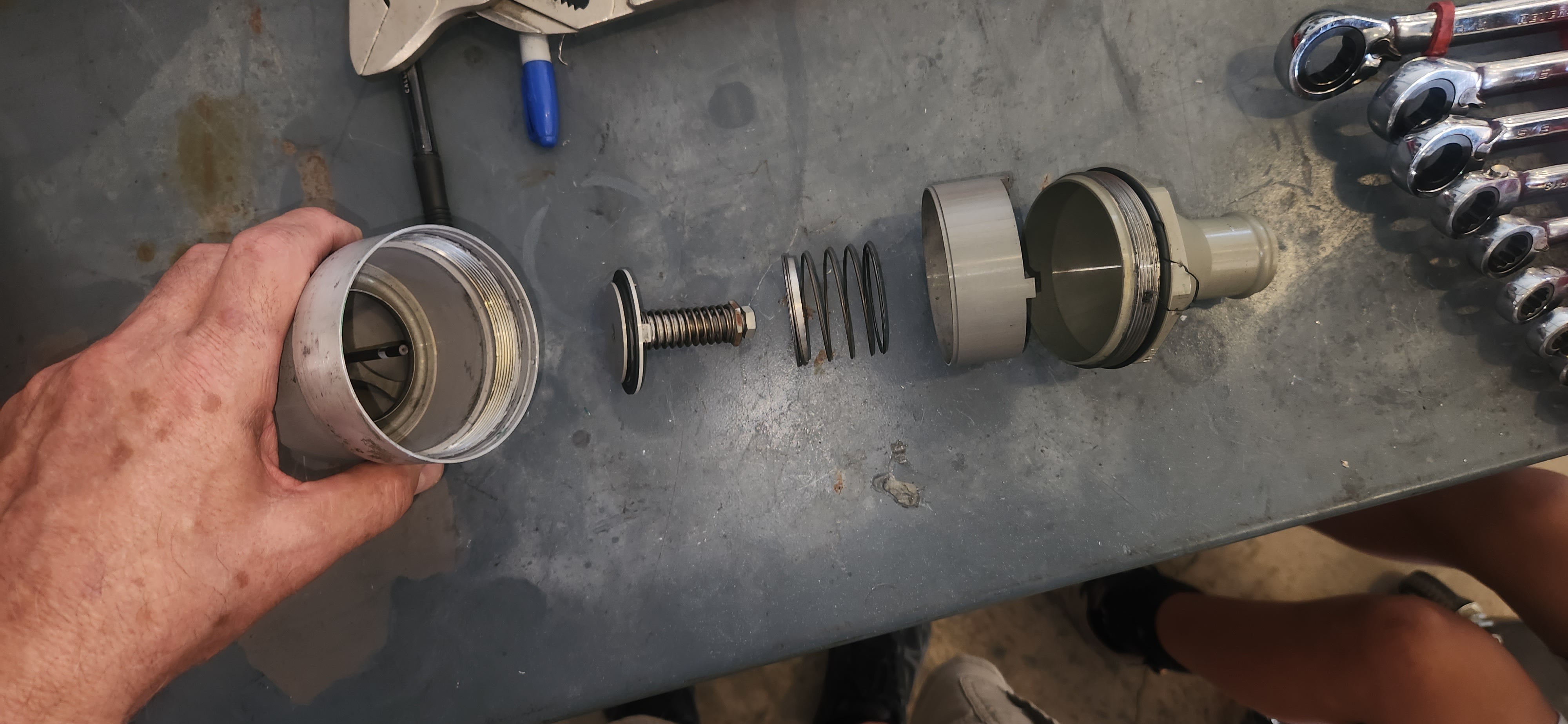
Here is a summary of our 4 failed valves.
_________
AERO DYNAMIC-
SIRENAGE – (we did a complete removal of inboard and outboard slats to install all new seals and Sireage strips)
NACA SCOOPS (inspected)
Landing light cooling ducts (inspected)
GEAR DOORS (found RMLG Followup door loose, tightened 1/2 turn.)
FLAP FAIRINGS. (found one on the right flap canoe loose. replaced springs)
LANDING LIGHT LENSES. (found them loose, 1/4 of the way around, both lenses. removed and re-bonded)
SLIPPER FAIRING ON TAIL (it cannot be felt in the rudder pedals)
STRUCTURAL
EXTERIOR PANEL FAIRINGS (removed inspected most likely fairings)
PRESSURE RELATED -WATER
AIR PRESSURE RELATED-
DOOR SEAL, WINDOW SEALS (2.5 PSI diff and greater, door should be well seated by then)
DRAIN VALVE BOX (should be below galley, looking for this)
HYDRAULIC – P. brake valve at VIP right elbow. (Does not make a hammer sound)
FUEL PRESS – UNWANTED VENTING (definitely possible)
FAN (Earlier, we found a wire harness ticking on a fan)
MED DOOR SEAL (performed complete disassembly and reseal of MED seal and pressure seal box)
TEMPERATURE-
HOT COLD MIX, DUAL VALVES (seems to happen well before valves come off the cold limit)
CROSS OVER DUCTS (it is back at Frame 25)
CONDITION TIED VALVE (it is in the correct area, but we do not suspect this)
_____
Some variables to investigate:
Aerodynamic
Speed
AOA
Maneuvering – climb only
Antenna loose, sealant ( performed visual inspections)
Pressure
Cabin diff(2.5 psi to 7, as far as we can tell. I drive the cabin pressure all over the place on a test flight….would not duplicate)
Hydraulic, park brake valve
Conditioned air, flapper valves (cycled valves)
Reading light fans
Park brake( i am not willing to set the brake in flight)
Neg press @ aileron(not likely)
fuselage Side drain tubes from Frame 8 to belly (?)
Sink drain (coffee maker does not make noise, we cannot locate the drain box yet)
BAG ISO(located frame 25, too far back)
Definitly repeatable on the ground. Most obvious when ATIS is beaking the com squelch, but no ATIS voice.
When 3rd crew audio panel is unplugged, noise goes away. Pretty repeatable.
When PIN D is pushed out of the 3rd crew audio control plug, problem goes away.
Problem solved itself after 2 hours of troubleshooting.
Figures.
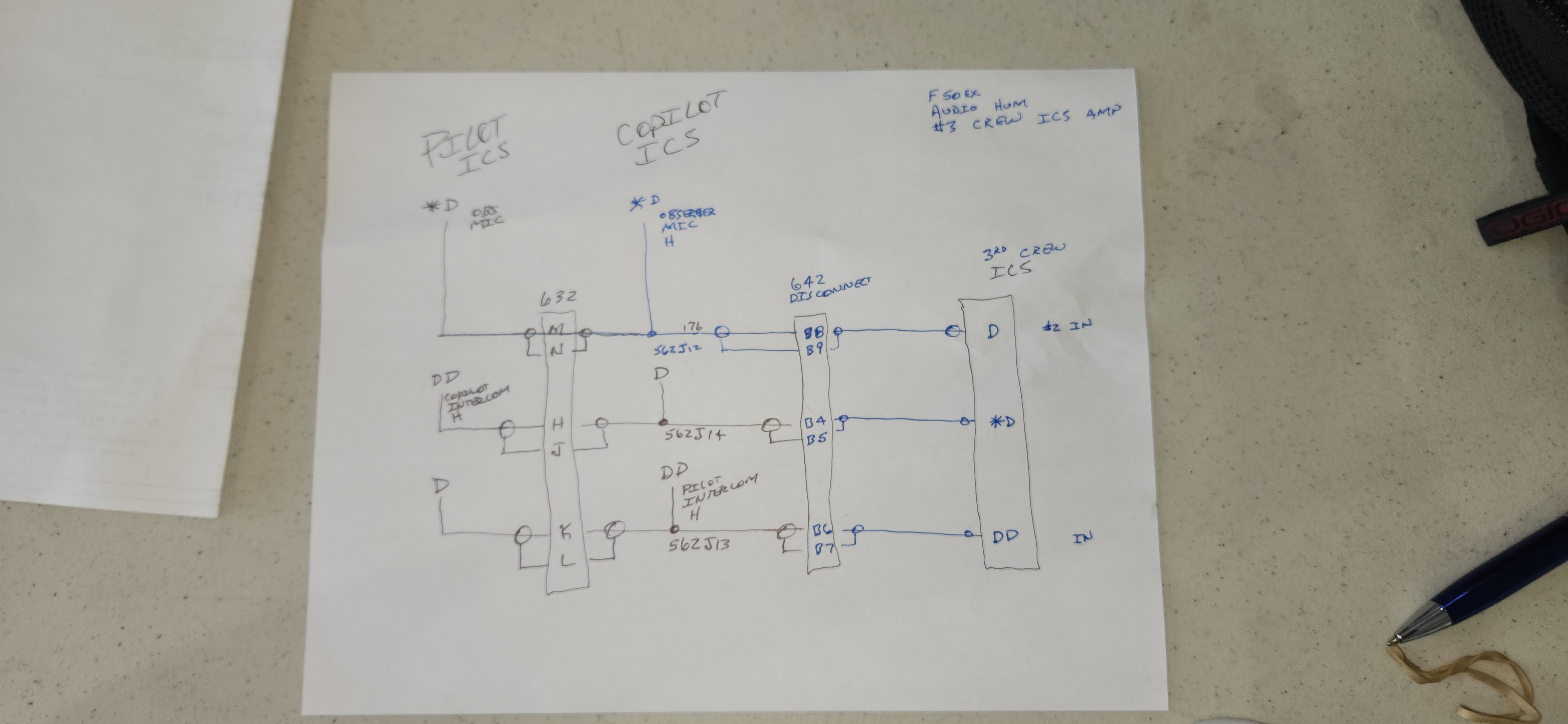
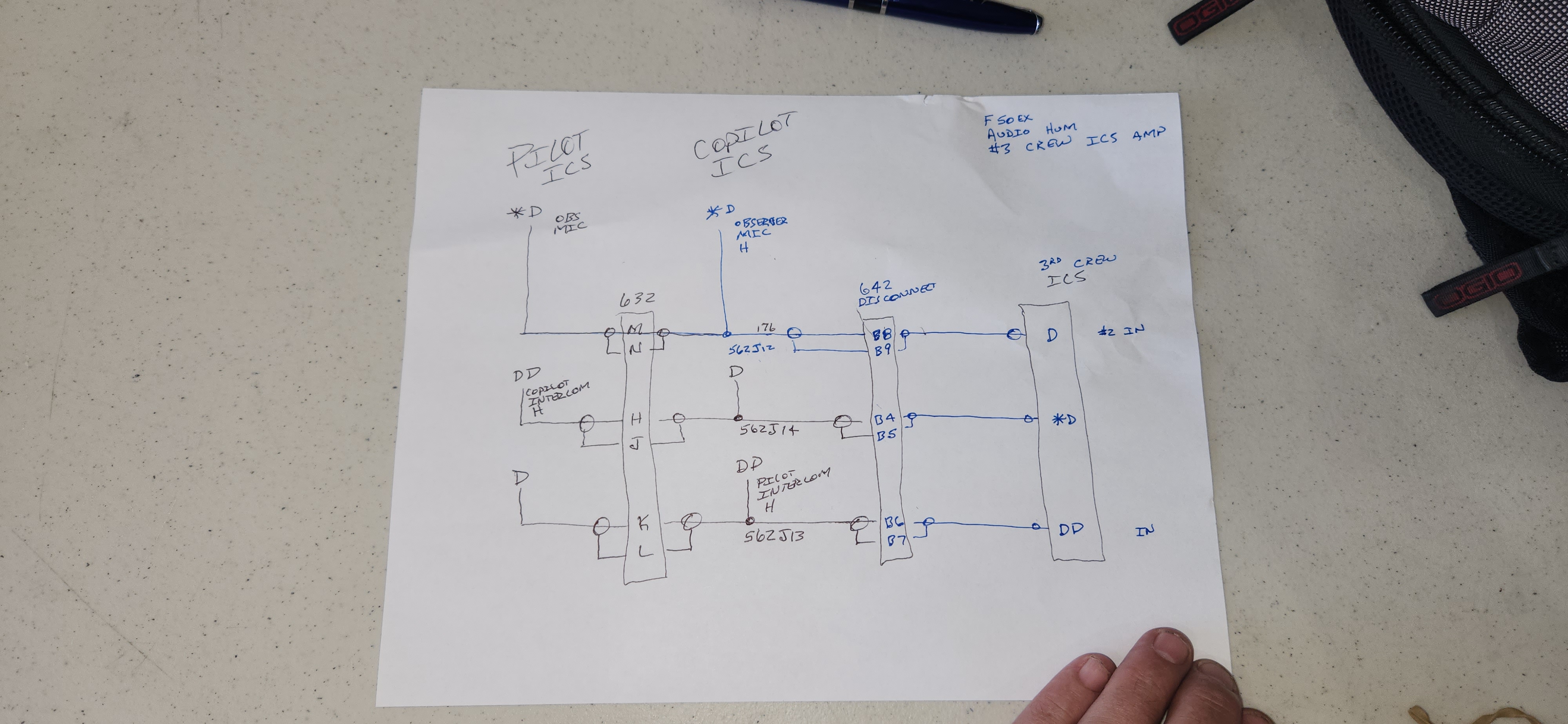
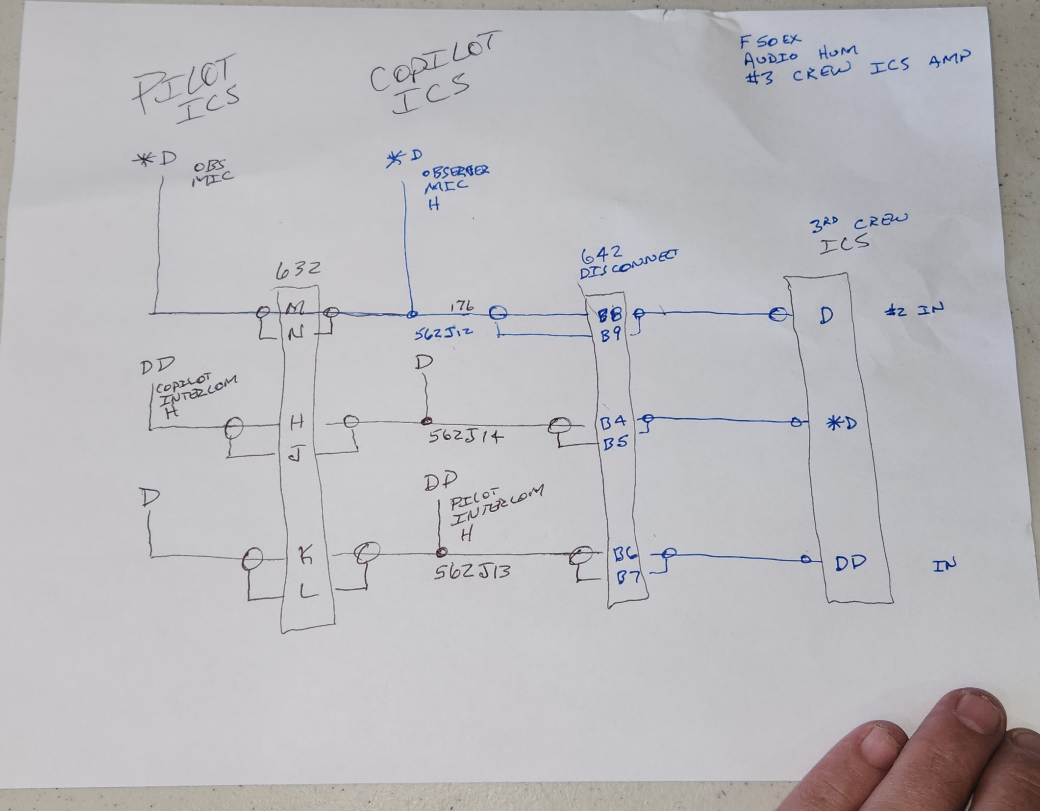
Later , pin d and another pin(ics) wer found swapped by the dom.
The squad has now morphed: RadAlt (EGPWS?) audio very low. There is still a hiss after ICS squelch break,and after ICS voice ends. Same with ATC audio.
May 7 leg 1.
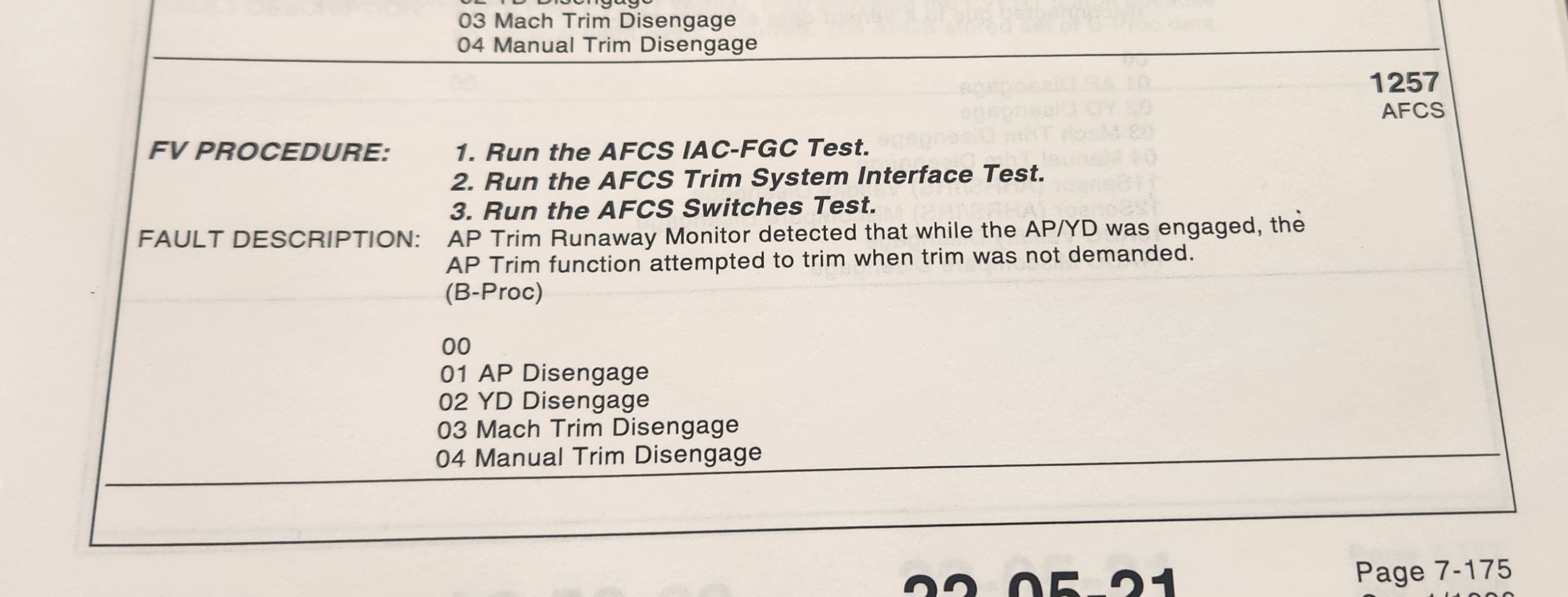
Closer look at 1257 01 follwing AFCS dissconnect.
Less interesting is Radar data bus
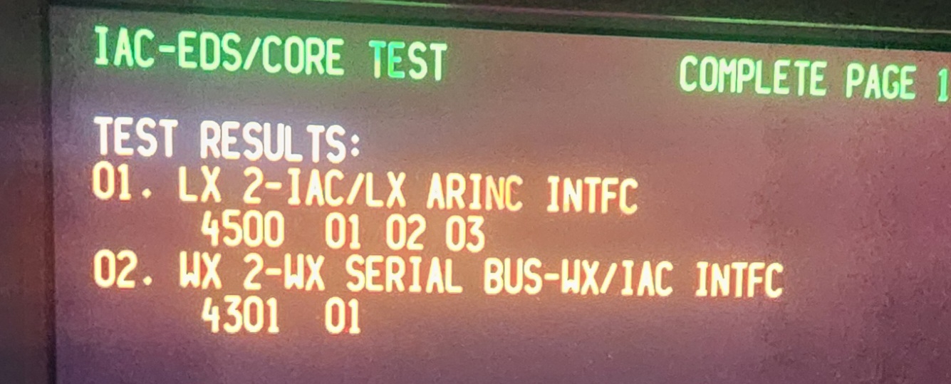
Now, IAC 1 and IAC 2 are swapped.
After much troubleshooting, this is the simplest squawk we can get:
AP will occasionally “release” the pitch control. AC might drift down at 100 ft/min. Pilots can gently pull up on the yoke and regain altitude. The yoke is “free”, as in no drag or contercommand from the pitch servo. During this time the autopilot will remain engaged. (Later note, this part of the squawk ONLY surfaced after Pitch servo exchange)
______________________
Initial investigation will be
1. Wires from the FGCs to Pitch servo.
2. CWS mode engaging for some reason.
3. The exchange pitch servo has a different squawk than the original. Suspect failed exchange servo.
————————————
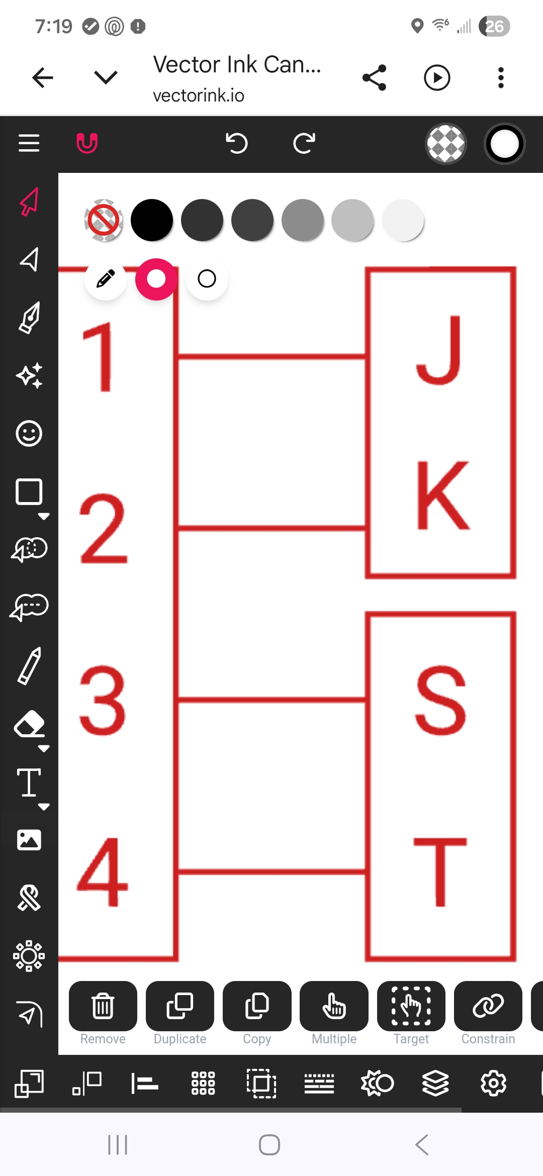
Stick figure for SPZ-8000 CPL
What are the other troubleshooting guidelines for the SPZ-8000 in F900? | toddheffley.com
http://toddheffley.com/wordpress/?p=6540
2nd line has the stick drawing for AFCS 1 2.
__________________
Reading the codes:
This one runs under Libre Office:
SPZ-8000-Flight-Fault-Summary .ods
This one runs under excel:
Jeremy Clary, his son Corbin will be organizing. 210-324-8311
Josh, is a director at ResCare. 940 305 6536
Todd Heffley 817 845 0145
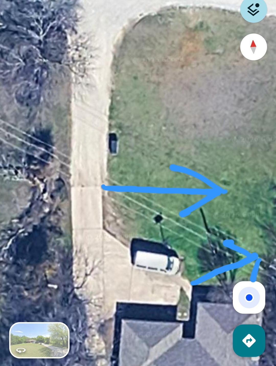
Pin in Google maps: