
Category Archives: AircraftTroubleshooting
seat parts for a Falcon 900EX
| grlowe@avfab.com,
|
We are looking for a Cable P/N MC6424-00. It is the lateral track release cable from a Model 5000 seat installed in a Falcon 900 EX.
Byt squawks at Portsmouth.
1. Hyd. pressure gage 2 inop. – Number 2 hyd gage dead below the zero peg until it warms up. PN 5502-360-80-10 SN 764, then it started working half way through our troubleshooting. rang wires.
Number 1 gage will not go to 2100 lbs with the AUX pump, hangs at 1600 lbs until you tap it. video. PN5502-360-80-10 SN 765
2. Number 1 engine ignition – L3KK left ignition switch. 820UN01S1BAOA. IPC 31-11-30-21 . SO number 403787. 1 gage only. ref.
3. Printer cockpit jammed – fixed paper jam
4. Look in radome – visual inspection good
5. Landing LED taxi – provide quote
6. ANTISKID Menelco. – Suspect moisture in nose axle.
7 . Overhead panels loose – resecured
8. Face on entry away light – Reinstalled face.
9. Light check , logo lights – LOGO lights not installed on this AC.
10. reevaluate possibility of repair for overhead panel. – paper overlay, month long repair removal.
11. change router password
What was the deal on the ALCON battery connector test pin.
.375 is pin
Old go/ no go was :
.370
.378
SB 101 from ALCON
Now company is called redling .
recommended not to use the old .378 tester. it opens the springs too far.
Instead, use a shoulder from a 3/8 inch bolt. Any tighter than slip fit is good.
Why would a Falcon 50 Passenger temp run away from HOT in AUTO mode
Complaint: Cabin cold in flight in auto mode:
EDIT squawk turned out to be : cabin cold in AUTO and in MANUAL.
I failed to realise early on that the cabin valve backing away from hot was normal operation. Also, when crew is max hot, the cabin backs down even lower. This also seems to be normal operation.
Observation: Pass Valve position needle will drive full hot, then immediately back down to half scale or lower. In the air and on the ground with APU.
EDIT 20/20 hindsight, this is normal operation. Also, it is exaggerated when the crew valve is toward hot. Who knew?
At about :40 seconds the valve runs cold on its own.
Reference:
F50 Pass temp electrical: f50passtempcontrol
Associated:
With the flood duct open, the problem is reduced.
EDIT: with the flood duct open, the cabin will quickly overheat.
With CABIN and CREW valves selected OFF, the problem goes away.
With a SEPARATE temp sensor plugged into 163H, hanging in free air, THE PROBLEM GOES AWAY. THIS is the ONLY way we have affected the squawk.
Troubleshooting so far:
We have shorted 162H AMP pin A and B together. This takes the temp select system out of the system and commands full hot. Squawk remains the same.
Crew Bleed or Pass bleed or both yield the same result. Squawk remains the same.
AMP to 163H wires rung out carefully. M, H, J.
AMPs swapped cabin and crew. Squawk remains the same.
162H Temp select controllers swapped for a loaner unit, Squawk remains the same.
Back-pinned v to assure it had a solid ground during operation.
With amp unplugged, Ohm meter on M, H, and J Both halves of the sensor read ~89 ohms at max cold, ~124 ohms at max hot.
Unrelated?
pulled 5 temp switches for a unrelated bleed oheat light when wing heat switched off, turned out to be a sticking PRV
Unrelated?
Removed failed seals at upper and lower turbo cooler Best-O-Bell inlet pipes. Installed 4 each new seals.
PARTS OFF: P/N 460-150 S/N NA.
PARTS ON: P/N 460-150 REV P LOT# 0110336483.
Performed leak check.
Quoted text from John Taylor:
- Leading Particulars.
Type of Control …………………………………………………………………………………………………….. Pulse modulated
Temperature Selector Range ……………………………………………………………. 60°F to 90°F (15.4°C to 31.9°C)
Input Voltage ……………………………………………………………………………………………………………… 18 to 32 VDC
Maximum Output …………………………………………………………………………………………………. 2 amps at 28 VDC
Ambient Temperature Range ………………………………………………………………-65°F to 165°F (-54°C to 72°C)
Deadband ………………………………………………………………………………………………………………….. 3.0°F (1.7°C)
Transient Voltage Protection …………………………………………………………………………………. + 80 volt, -600 volt
Reverse Voltage Protection ………………………………………………………………………………………………………. Yes
Output Protection …………………………………………………………………………………………………………………….. Yes
Hi-Limit Protection ………………………………………………………………………………………………………. 160°F (70°C)
Cabin Sensor …………………………………. Negative Temperature Coefficient Disc Thermistor ( See Figure 1 )
Temperature Readout Sensor ……………………………….. Wire wound positive temperature coefficient 0.2°/F
Construction …………………………………………………………………………………………………………. Repairable Assy.
Connector Type …………………………………………………………………………………… Mates with MS3120A-14-195
Size
Length (max) ……………………………………………………………………………………… 8.400 inches (213.36 mm)
Width (max) ………………………………………………………………………………………….. 3.900 inches (99.06 mm)
Height (max) …………………………………………………………………………………………. 3.225 inches (81.91 mm)
Weight (approx.) ……………………………………………………………………………………….. 18 ounces (510.3 gm)
Temp Amplifier simplified block diagram:
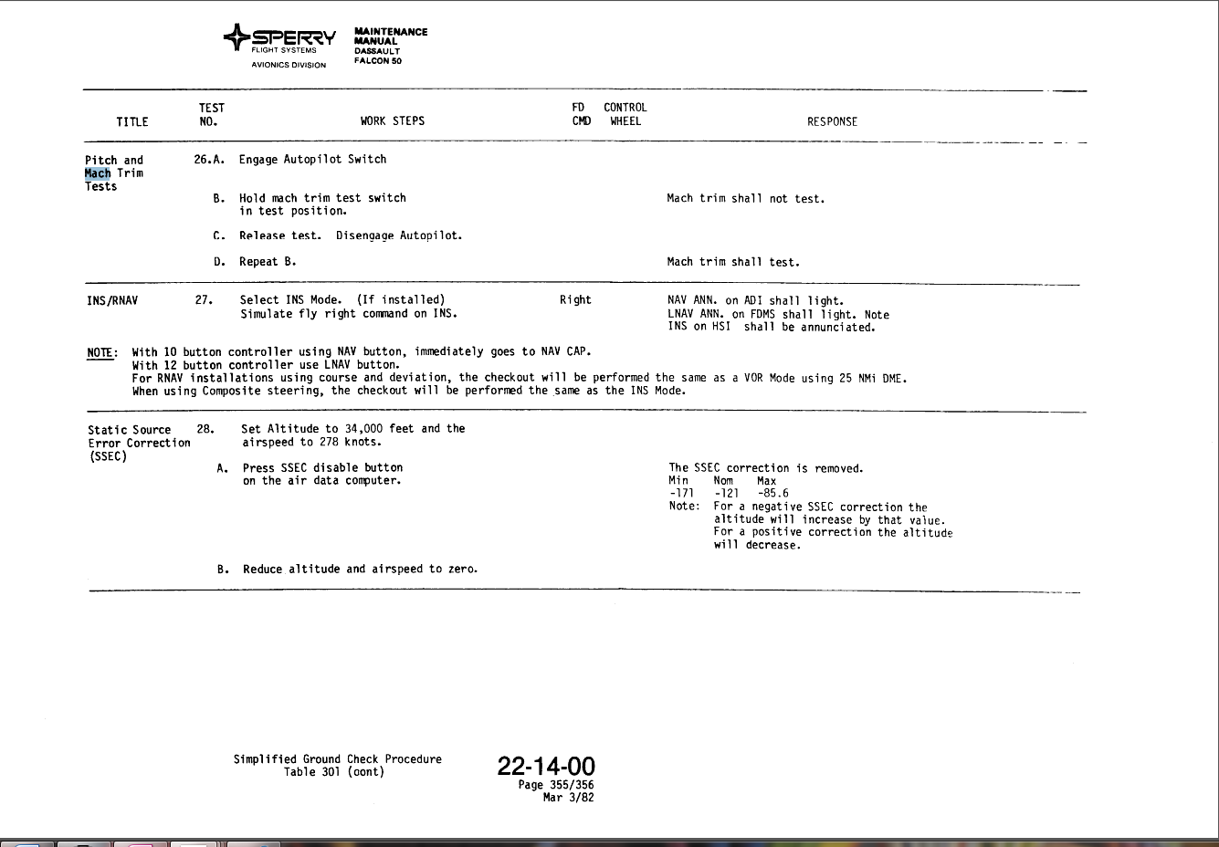
How in the world do you maintain a F50 with Sperry SPZ-600
What are a few of the items that need to be done for a N Number change
Registration change
Change FAA registration number to N—–H(?).
Change painted number on fuselage.
Fabricate placards for cockpit.
Strap change ELT to new ICAO number.
Send ELT to be reconfigured for new N Number.
Assure life raft ELT’s are registered properly.
https://beaconregistration.noaa.gov/RGDB/index, you need a login and the ELT HEX ID.
Strap Transponders to new ICAO, ADSB Strapping

http://www.avionictools.com/icao.php
Change N Number in FMS setup page(?).
Assure AFIS is configured for new N Number or deactivate AFIS.
Change N Number at EFIS maintenance screens. (NA for Primus 2000)
Verify Airshow does not display old N Number.
Update Camp registration.
Verify RVSM manual does not require update.
Change CAMP regularly. Number, HAPP CASP enrollment.
How can i check the start contactors for 28v and ground on the coil?
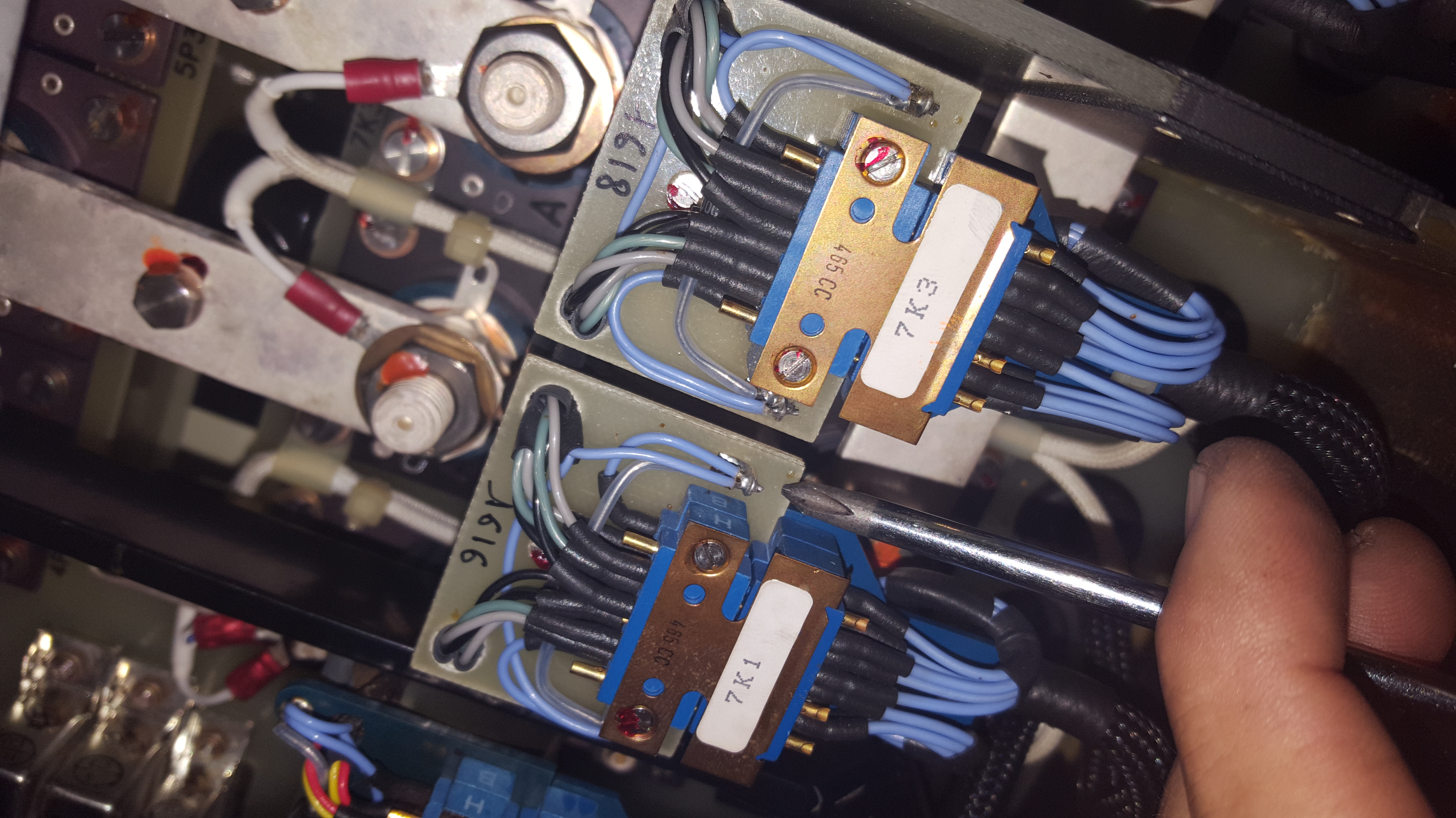
These two small studs are the wires for the field colapse diode across the coil.
The diode here below the wires. It is not significant to your troubleshooting, but the studs are.
You can attach the leads of your troubleshooting light to the studs, and you are watching the coil voltage.
Why does the door pop on a f900 during climb?
There is a HUGE amount of pressure that pushes the door outward when the airplane is pressurized. It causes the feet to lock in place then jump a little as the fuselage grows with pressure. The feet must be perfectly polished and clean to prevent this. There must be a SMALL film of grease on each foot.
This is the dome shaped foot on the door.

This is the flat foot on the air-frame. interestingly it has a slight pattern of vertical lines that are worn away on the contact patch.

the tiny polished spot is the contact patch
The contact patch for each foot is only about a quarter inch around or less in some places
looking at the pressures applied to these feet:
Door is about 34 inches by 80 inches.
2720 square inches, 9.1 psi of pressure,
24752 pounds pushing out on the door.
10 door stops, so about 2400 lbs pushing on each stop.
.25 X. 25 inch contact patch means
2400lbs / .0625 sqin = 38000 psi pushing on each contact patch …….
.
Floor tape, teflon tapes
Floorboard tape, watersealant tape, corrosion prohibitant
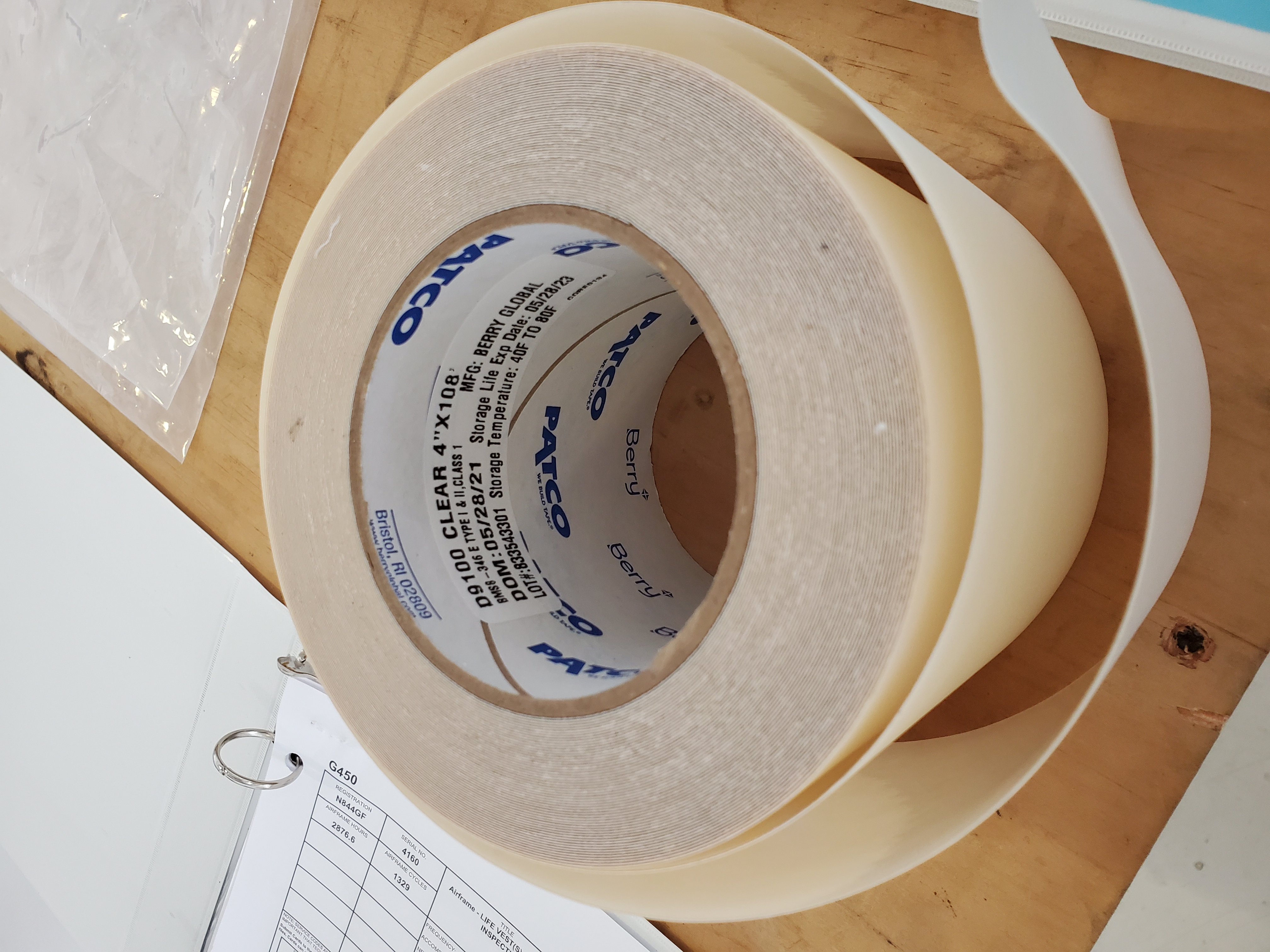
Fibre glass tape
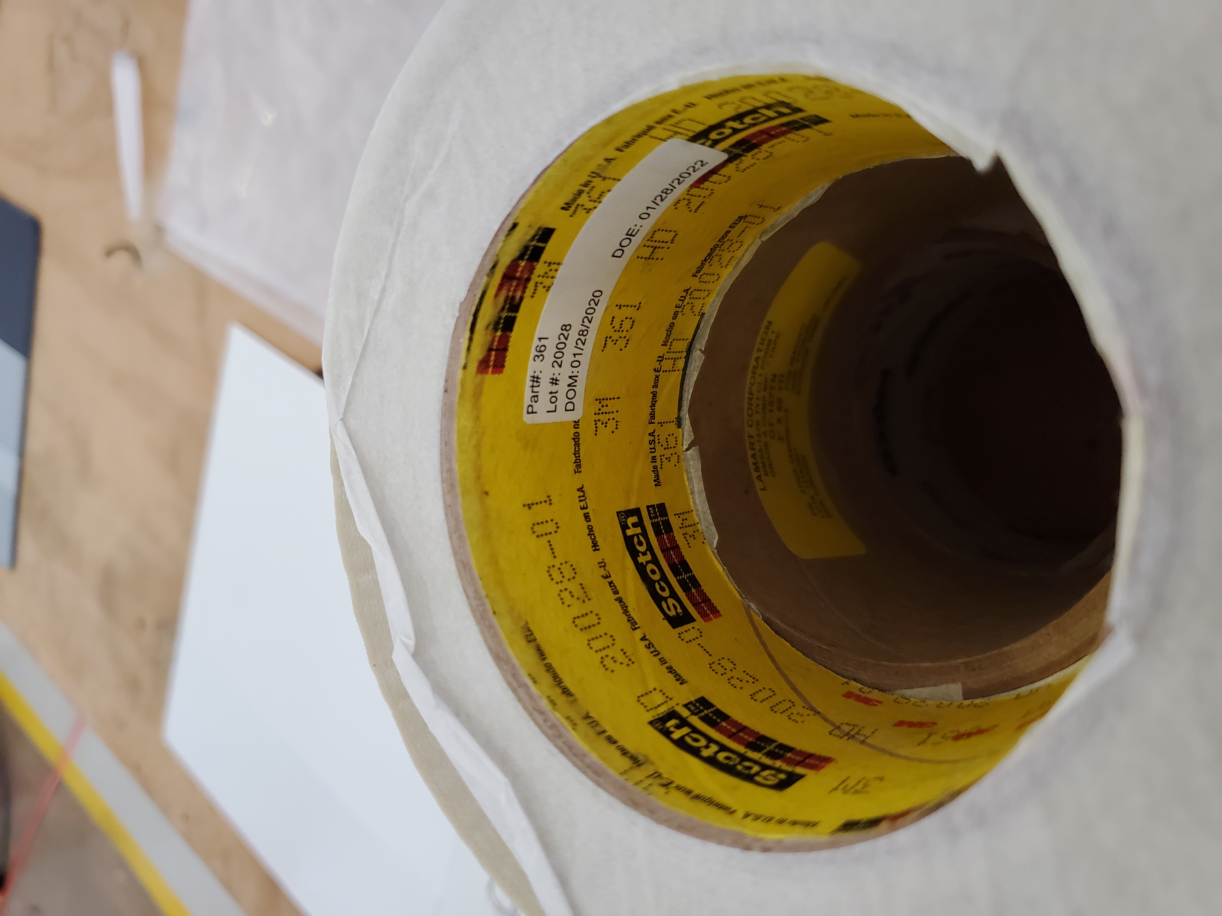
Thin white tape with fibre reinforcement. Very dificult to remove.
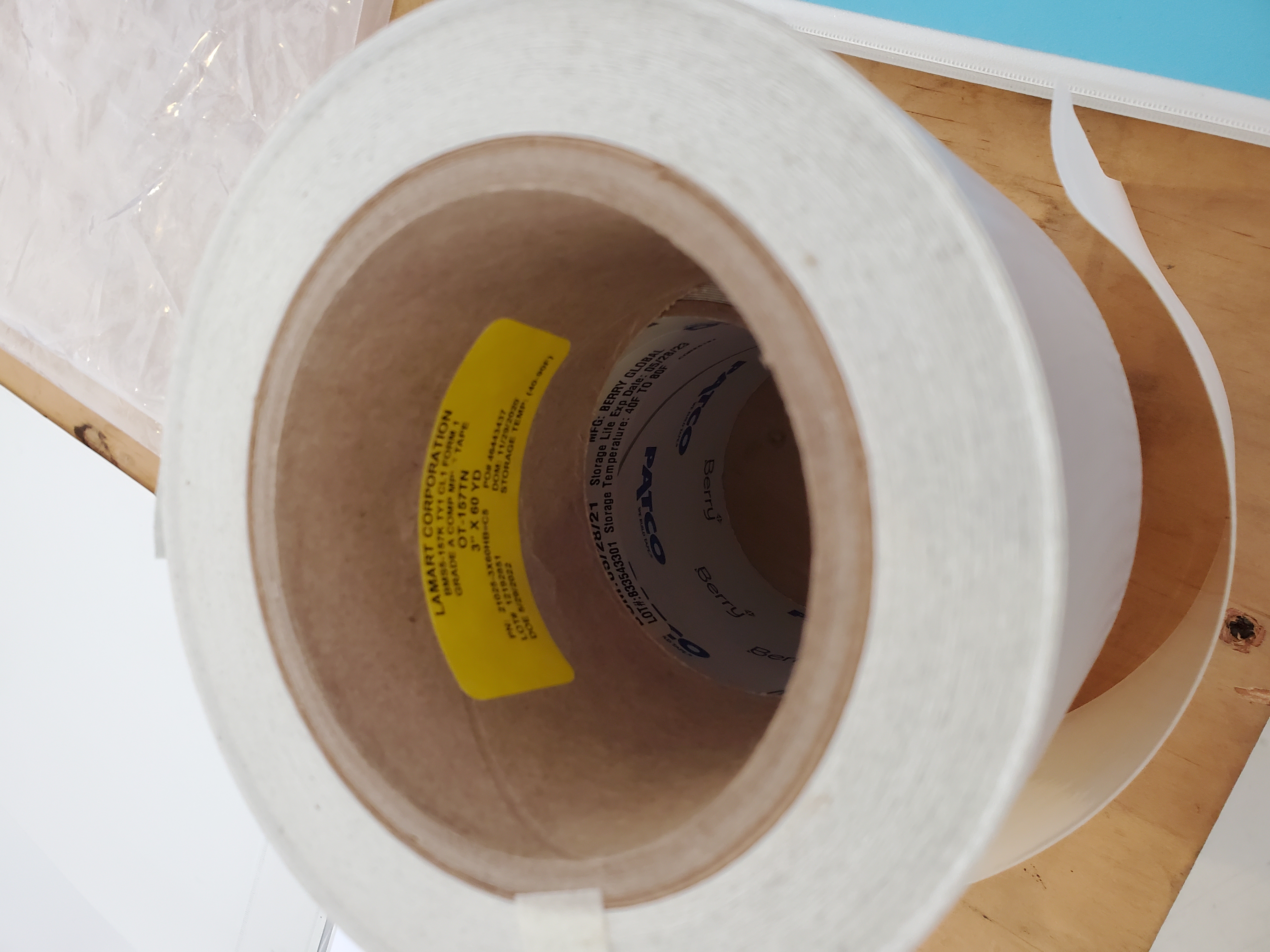
Black floor panel tape at gulfstream G450 near gear well aerea
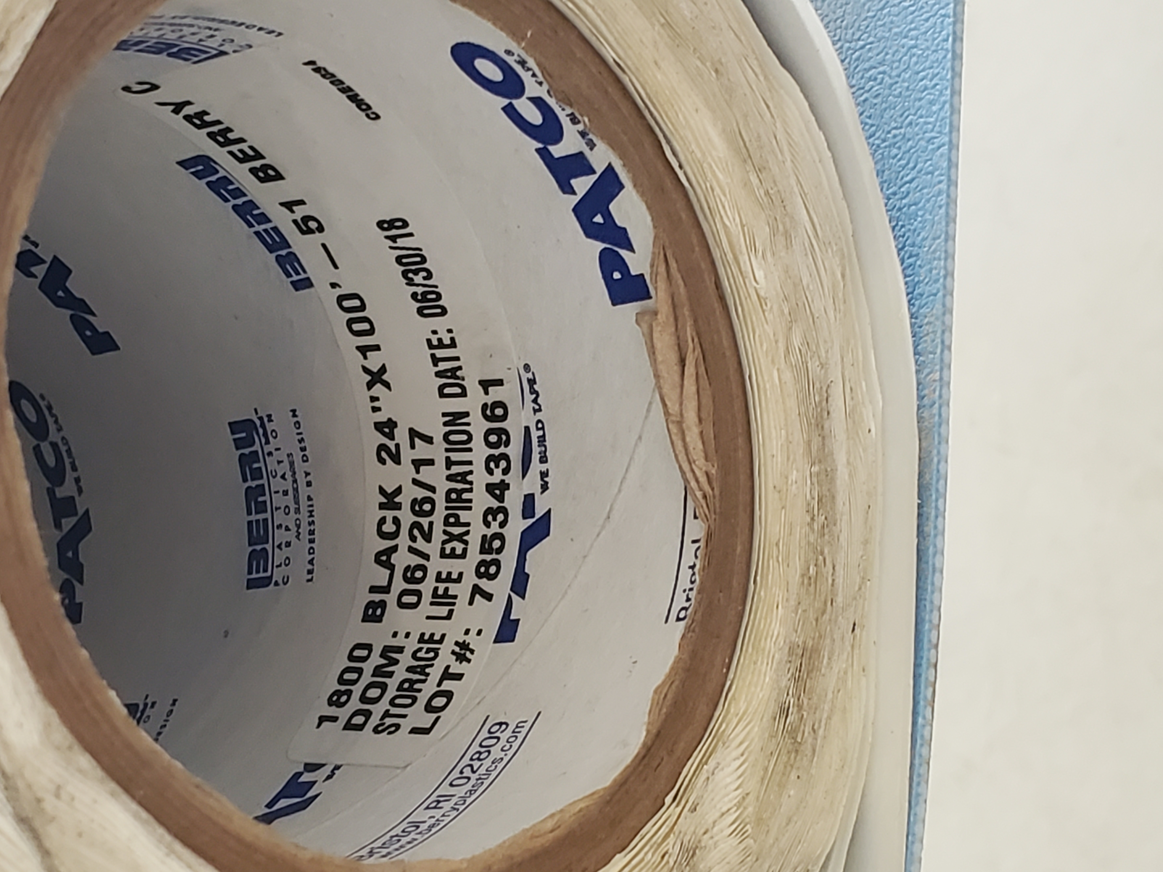
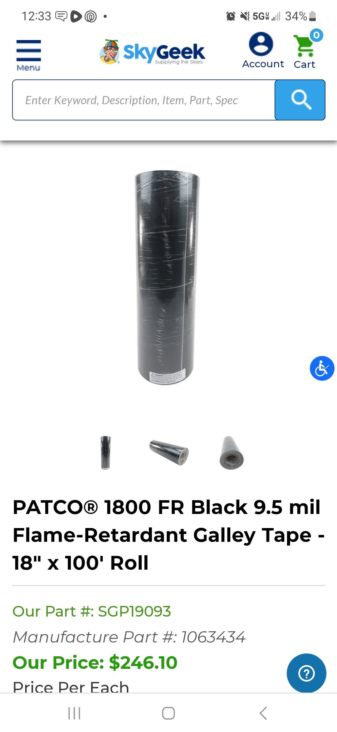
black neaprene tape on baggage door.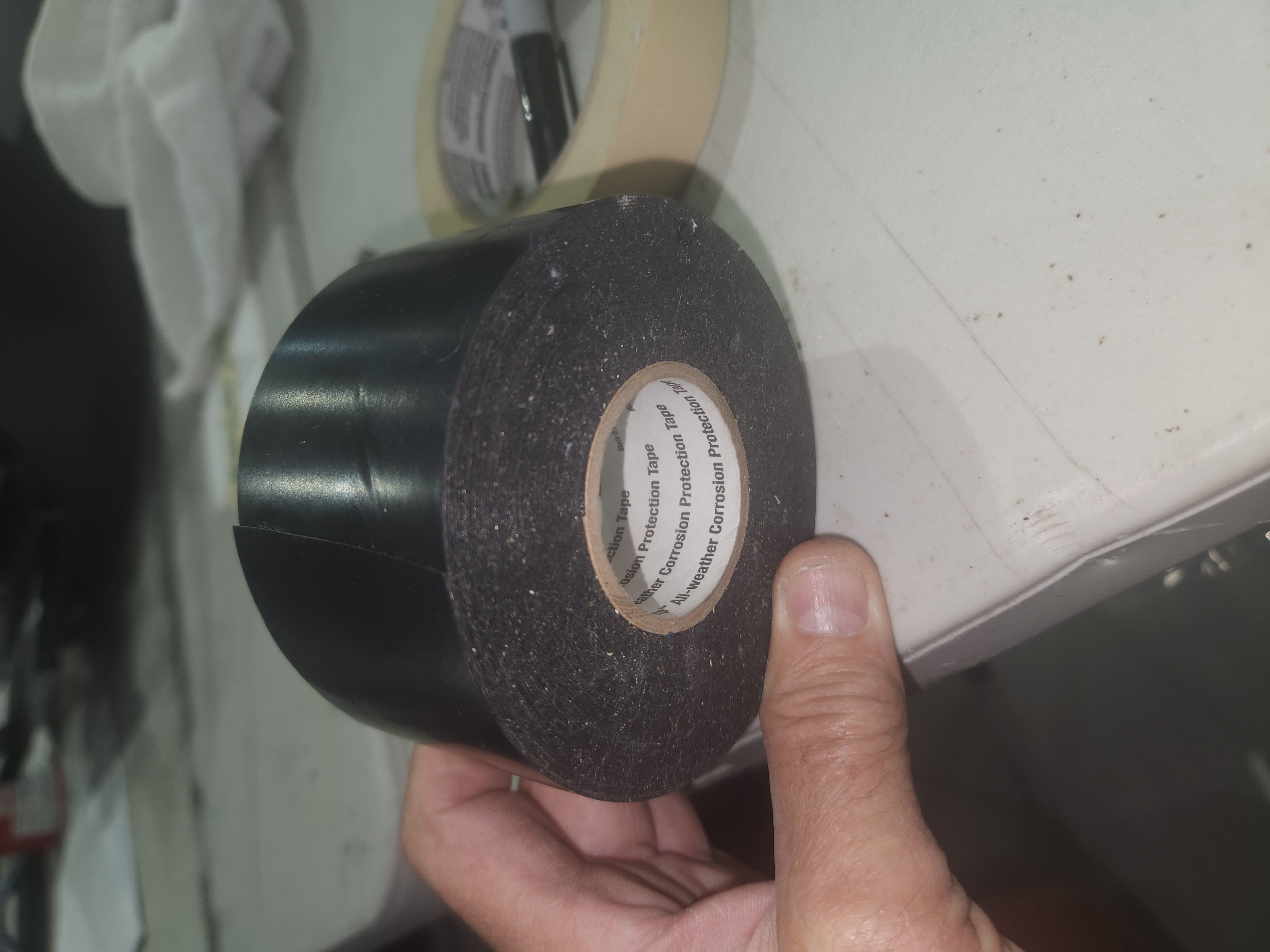
Gulfstrem leading edge tspe, good for floors Continue reading Floor tape, teflon tapes