g280 p1 plug 2403-D38999/20FH55PN-ND
-18-31S. H.
M83723/77R 1831 N

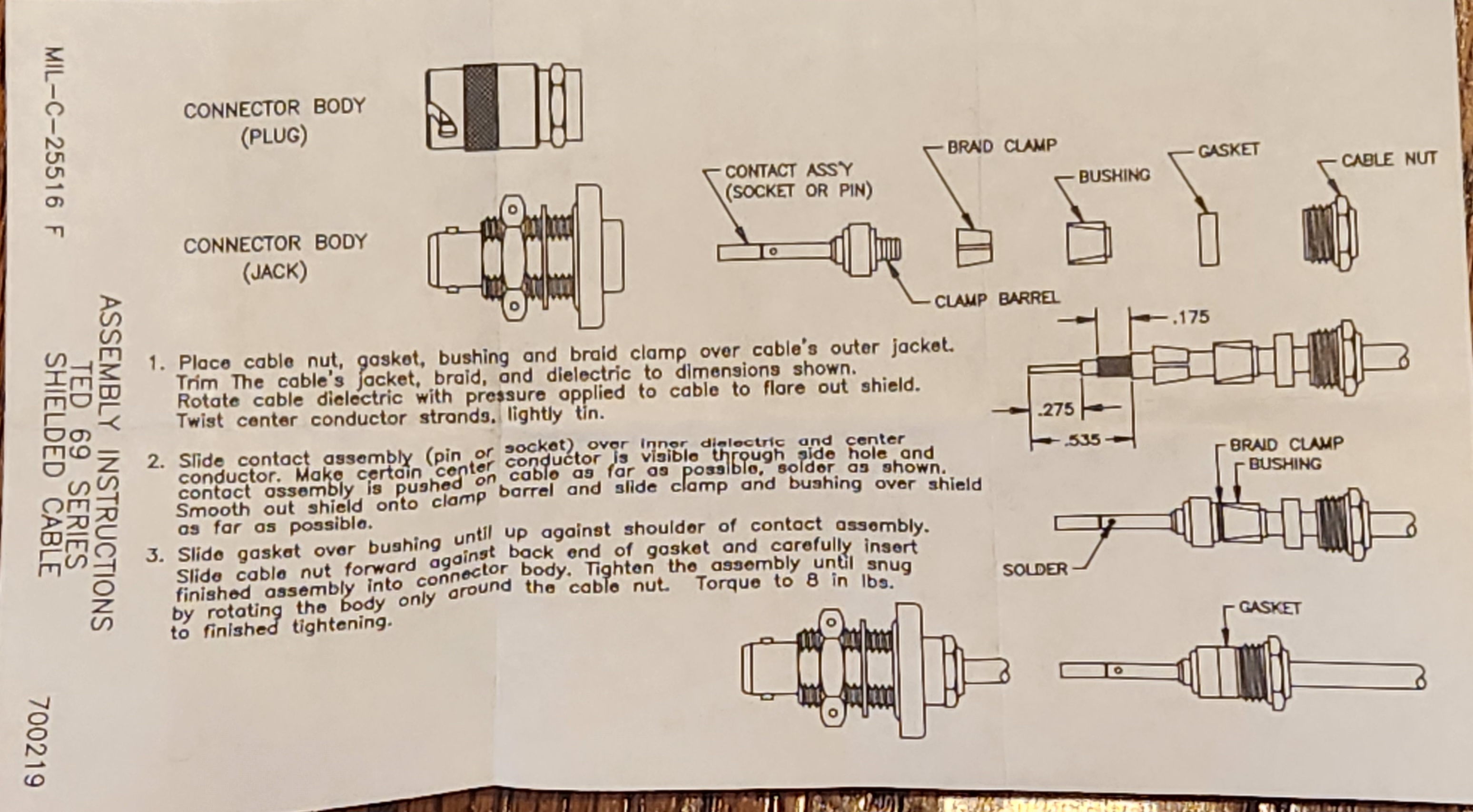
This is a different brand TED connector.
1211-422-POL-F
Made by CNL
This 101-011434 box has both wing and gage side


 ì
ì
TED connector
g280 p1 plug 2403-D38999/20FH55PN-ND
-18-31S. H.
M83723/77R 1831 N
This is a different brand TED connector.
1211-422-POL-F
Made by CNL
This 101-011434 box has both wing and gage side
ì
TED connector
Falcon 10 N100CU, Leading Particulars:
AP105/FD109. Dual FD. Single FMS.
AP AMP – 562C-5C.
PILOT AIR DATA CONTROLLER –
COPILOT AIR DATA CONTROLLER –
Pitch bump started, May 2022. Swap vg. That solved it for months.
Pilots report all good.
Swap airdata controller. (Back to original position)
Hum in headsets
Stuck mic. Seemed to start pitch bump problem.
Mar 2023. Shutter pitch, humming headphones, could not hear atc. Stuck mic.
______________________________________________________________________
after finding burned plug at RH lav:
#1 FD/AP will not capture altitude, but (sortof) will track altitude
#2 FD will not GA. RH GA will clear HDG select button, will not clear ALT select button. When RH GA is held down, RH Vbars will go to 0 pitch or lower, then disappear when G is released.
GA mode block diagram Falcon 10
inputs to the mode coupler seem similar left side to right side.
WD notes from Nov 2023.
Collins manual that shows the difference between 590A-3H, and 590A3K
1.5.16 590A-3H Air Data Control
The 590A-3H Air Data Control supplies an analog error signal to the flight control system that is propor-
tional to altitude error. True airspeed, indicated airspeed, and altitude programming voltages are also gen-
erated for flight control system use. The altitude error gain may be programmed with true airspeed, indi-
cated airspeed, or altitude, or set at a fixed value. The 590A-3H also provides signals for altitude preselect,
vertical speed hold, indicated airspeed hold, and Mach hold. The 590A-3H is contained in a 318-ATR short,
low case and weighs 2.09 kg (4.6 pounds).
1.5.17 590A-3J/3J1 Air Data Control
The 590A-3J/3J1 Air Data Control supplies to the flight control system an analog error signal that is propor-
tional to altitude error. True airspeed, indicated airspeed, and altitude programming voltages are also gen-
erated for flight control system use. The altitude error gain may be programmed with true airspeed, indi-
cated airspeed, or altitude, or set at a fixed value. The unit is contained in a 3/8-ATR short, low case. The
590A-3J weighs 2.00 kg (4.4 pounds) maximum. The 590A-3J1 weighs only 1.5 kg (3.3 pounds).
Falcon 10 AP disconnect cockpit troubleshooting:
falcon 10 ap disconnect ts-1

1. Seems to have ALT HOLD working correctly, no ALT CAP mode.
2. CoPilot Side, NO GA mode, will no clear ALT button.
3.
Test Point Locations:

GA 562A-5M5, TP-16 Selection of go-around mode.
MDA, DH, or ALT PRESEL 590A-3H, J1-50 Descent blw RA
GS EXT 562A-5M5 TP-42 Following glideslope capture, with radio altimeter inoperative, and when passing over
middle marker beacon.
*ALT 590A-3H, J1-31 Selection of altitude-hold mode.
Conditions:
page 25 mode ANN
How good should it be? 25 to 45 feet, depending on mode.
page 28 How good should it be?
Test Flight:

1000ft/min climb select VS. allow to stabilize.
Record Video, altimeter, VSI.
Slightly increase throttle.
allow to stabilize.
Video Stop.
1000ft/min climb select VS. allow to stabilize.
ALT SELECTOR to 3000 feet above current alt.
Record video, Altimeter, ANN panel, V-Bars. Select ALT SEL.
Allow to capture. Do the VBARS capture? Does the autopilot capture?
Allow to track 1 minute.
Gently increase throttle.
Allow to settle 1 min.
Video Stop.
in HDG and ALT mode, allow to stabilize.
Record video, Altimeter, ANN panel, V-Bars. Select ALT SEL.
Select new heading on HSI,
Allow aircraft to turn for 1 minute.
Allow to settle 1 min.
Video Stop.
couple a ILS approach using APPR button.
video capture, pushover.
Stabilize on GS.
Slightly change throttle.
video GS needle action, mode ann, VS needle
SIL 2-74 FCS-105 FCS-105 Component Test Fixture
SIL 1-78 FCS-105 Adding 1/2 Bank Limit to FCS-105 May 15/78
SIL 1-79 FCS-105 Removal of TAS Programming from Heading Select Gain
Computations Jan 15/79
Date
Jul 01/74

Plug changeout
Floor board screws are
NAS517V4-8XA OR -8XF
Older falcon number is F50B201505079

G450 N809DA S/N 5269
ITEM P/N MFG QTY


Large 90 degree connector


Ground Run.
Galley light master, RH console not labeled clearly.
PBK2 INTERMITTANT. Works when you tap on it.
Exterior light check.
Dark cockpit dimmer check.
Intermittant rushing noise in headset ICS. is there a 3 crew hs plugged in?
#2 hf innor knob drags Outer knob. Clean, tighten knobs with a small gap
Bezel eexit sign back bulkhead loose.
push button cover at Auto prctlurization control head Missing.
AirBnB
https://scrantonseahorseinn.com/welcome/the-inn/
111 22222 33334 444 9090 3749 99999
Carter
Soundview or 55 exit
Strobe intensity
https://www.avionteq.com/American-Aerospace-ST-4000-Aircraft-Strobe-Light-Intensity-Tester
Aeronca 7AC Champion “Champ” N82258 S/N 886
The Aeronca Aircraft Corporation (AERONauticalCorperation of America) Produced 7,200 of 7AC “Champs” in 1945 to 1948. Derivative models are still produced today, as late as 2024.
The 7AC is a sought after antique, with thousands of flying example still airworthy.
The Heffley Family airframe is a Model 7AC, powered by a Continental A65. Superior cylinders were fit during the rebuild.
Weslyn

Recent Past:
Aeronca N82258 in various states of disrepair, during the term of a 8 Year restoration:


2006_02_08ChampPaintGoneBad
This is what happens when the paint process goes horrably wrong. This is the result of not sanding the primer after the last cote of primer. This video shows the paint peeling right off. We followed the STC exactly, and applied the first color coat over the last primer coat with no sanding. This is not wise, as we now know. Airtech markets its product as process that requires little sanding. While it is true that you are not required to sand as as much as Stitts, it still requires the coats to be “scuffed”.
2006_01_05ChampPaint
The Ailerons, and Elevators/Stabilizers, (not the rudder) installed on a spit for painting.
2005_12_29_ChampPaintBooth
We built a paint booth (Larger) from discarded metal studs and plastic sheeting. The intake is a 24″x24″x1″ AC filter with a box fan. (lowerLeft corner of the picture). The outlet is a filter connected to 1/4 of a LARGE cooling fan. This evacuates the booth, as well creates a draft in the hangar that cause overspray to go west out the doors. Interestingly, the outlet fan filter FILLS up every time we paint. No overspray anywhere in the hangar though……
These are the cable fairleads
that will provide a cosmetic closeout for the rudder cables as they exit the Fusalage under the stabilizers.
2005_11_27ChampWingSpit
This is the wing installed on the completed spit (larger). Copied from a comercial design, The rollers (larger) are metal lawn mower wheels with the tires cut off. The hoop is 1/2 inch electrical conduit bent with a conduit bender.
The wing spit is a complete success, allowing the wing to be coated fully on both sides without a 1 day wait for paint to dry. If we had to do it all over, 1″ conduit would have been stronger. Also, the rollers could have been lower, allowing the wing to be 3 inches lower to the ground.
2005_10_15ChampGear
Here is a  Sectioned (larger) gear oleo and strut. We used this for a reminder of how all the parts came apart!
The  Gear Case Frames almost ready to paint. We included the
 tabs for the snare cables, even though the AD is complied with……
2005_03_18_ChampStrutPress
This  press ended up not being required, as the gear did not need to be “Pulled” apart.
2005_01_08_ChampRightBrake
We disassembled one brake at a time, as they are quite complicated.  Assembled, Inside
  Exploded.
2003_Fuselage
Here is the Fuselage  before (Larger) Powdercoating, and one picture
  after (Larger) powdercoating
Later in the process:


Fly in mode change veil without transponder
EPIC
600 FEET on RA
PB 1 and 4, then TEST


