Actual FAR you are complying with:
from FAA website:
farther down
The FAA may give you credit for your practical experience after an ASI has reviewed your documentary evidence. Your documentary evidence must show that you meet the time requirements (18 or 30 months, as applicable) and during that time you gained actual experience with the procedures, practices, materials, tools, machine tools, and equipment generally used in constructing, maintaining, or altering airframes or powerplants, appropriate to the rating sought. The more documentary evidence you provide to the ASI, the better.
Documentary evidence is any record you provide that shows proof of training and OJT the practical experiences you have completed. Examples include:
Out of sequence Thrust Reverser lockout recovery
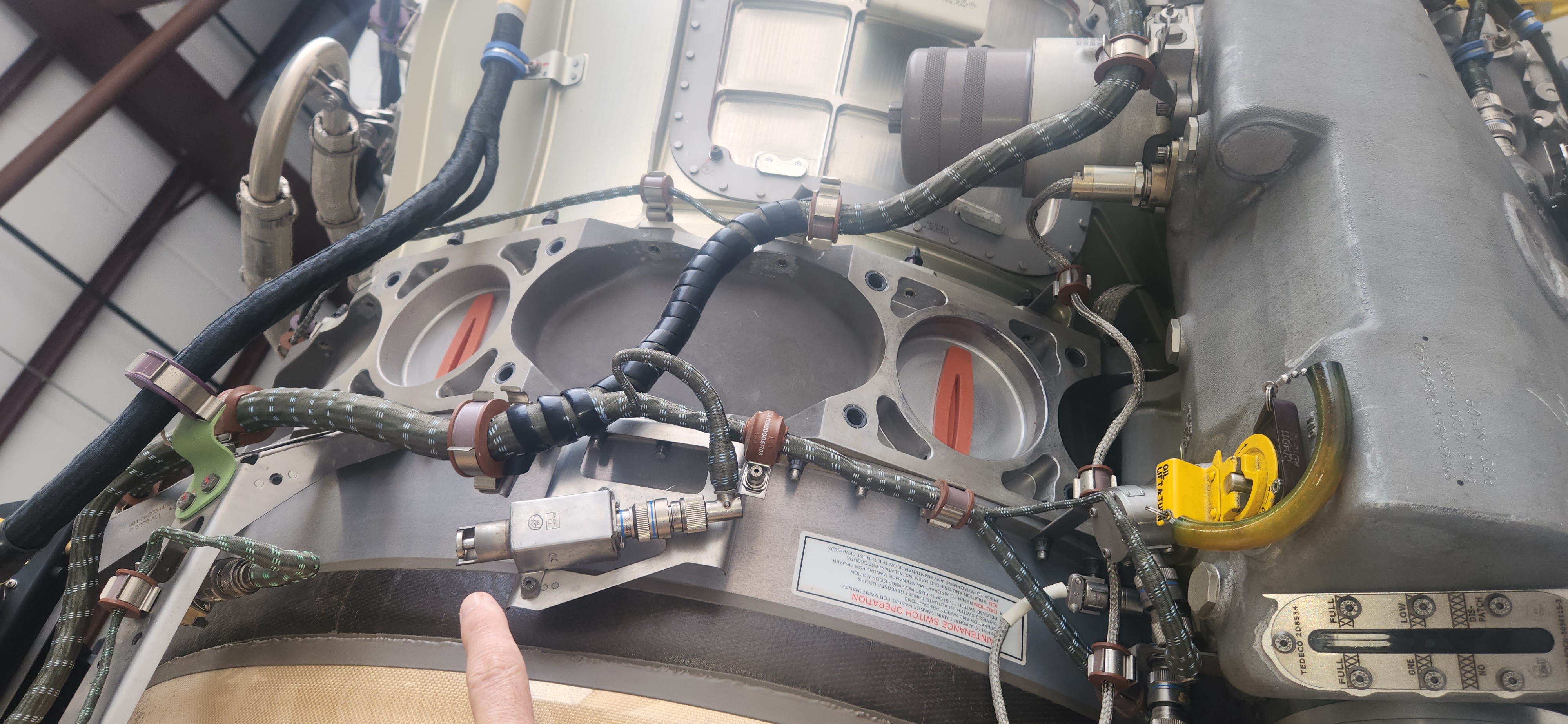
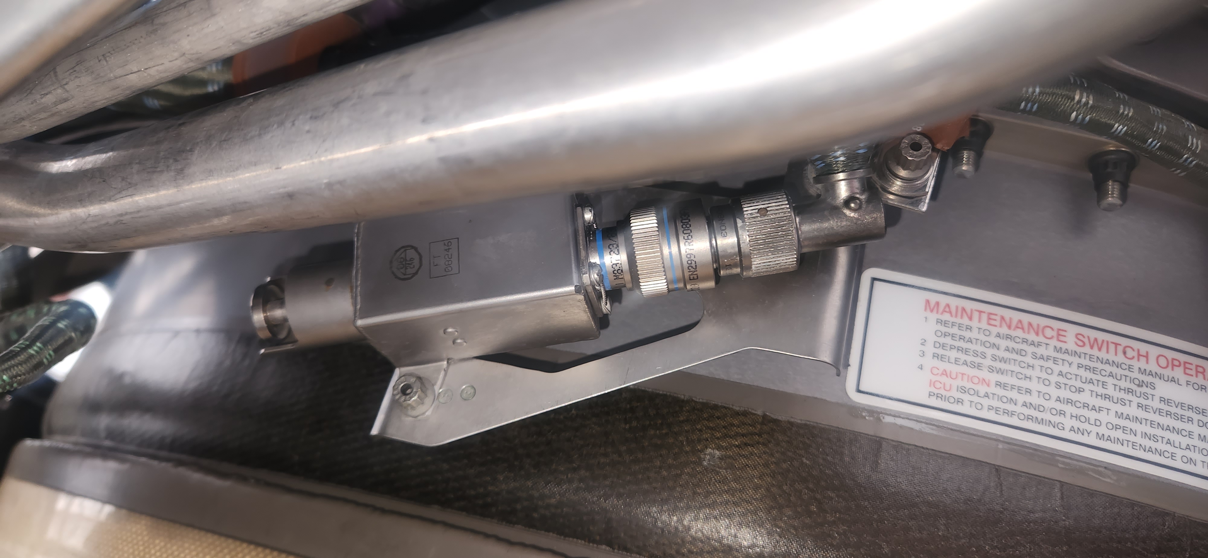
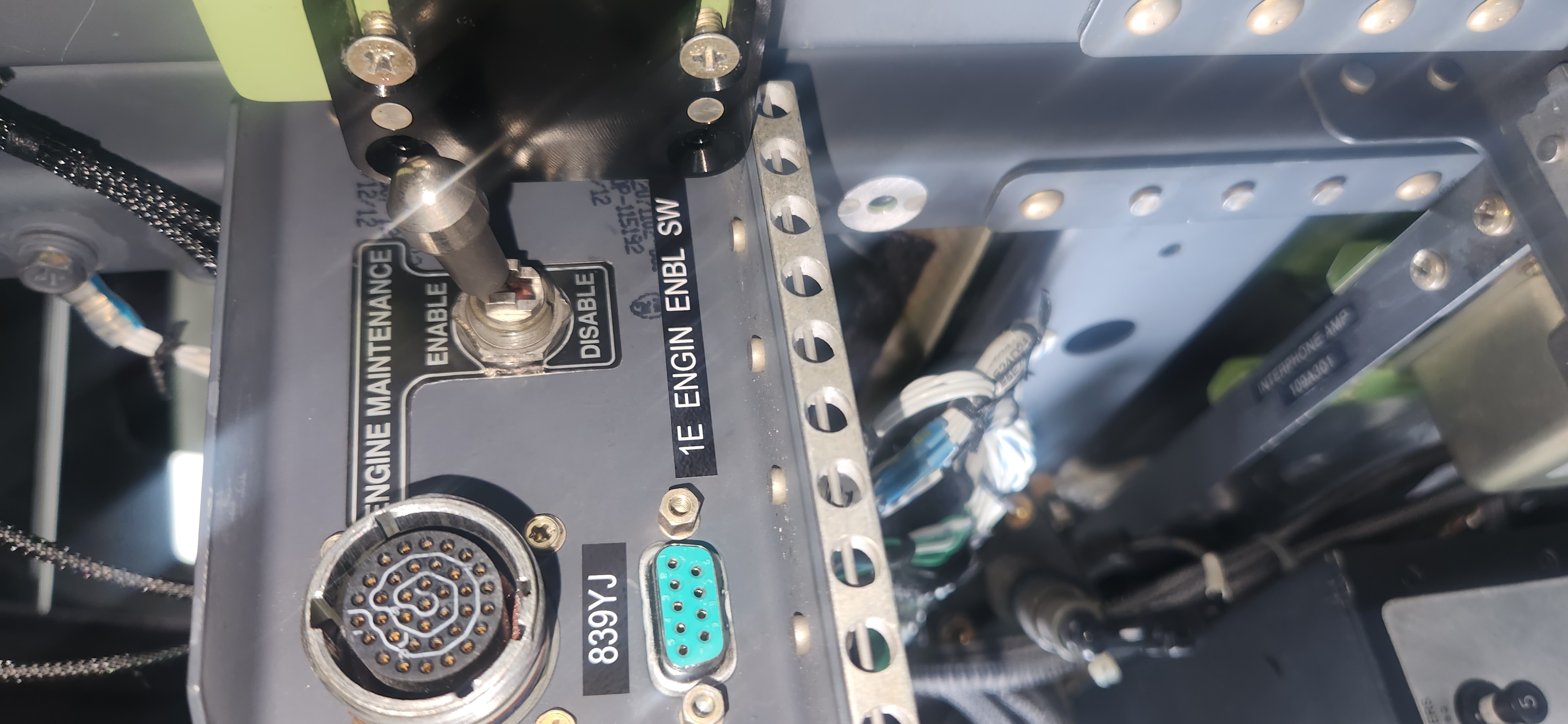
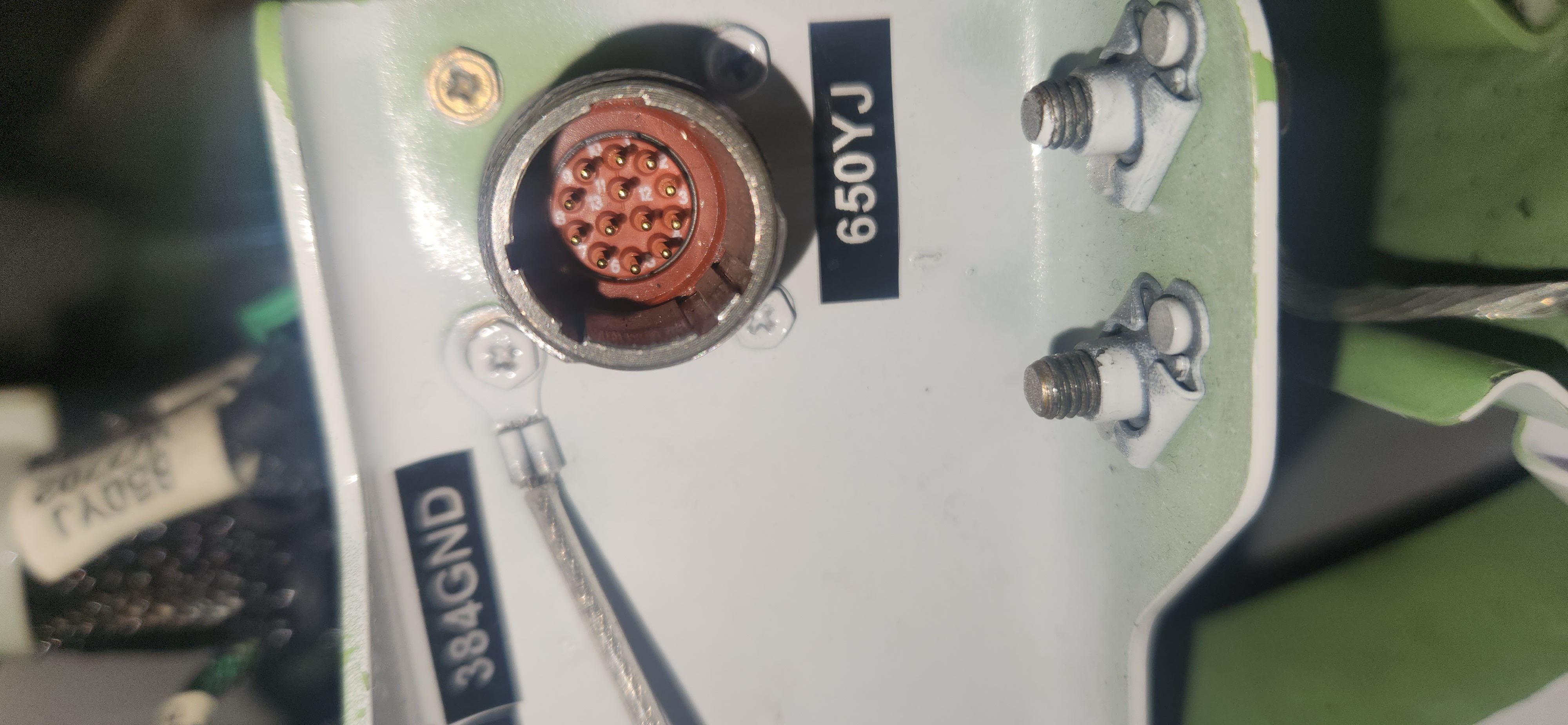
Maint Sw left closet to MAINT.
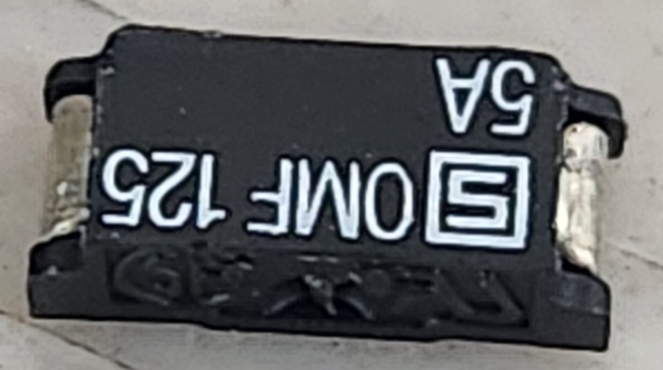
FADEC CBS out x4
Piggy Backs match TR position.
HYD ON
Bypass sw on engine hold down.
FADEC CBs PRESSED.
Piggyback to desired position.
TRs move.
Release bypass sw on engine
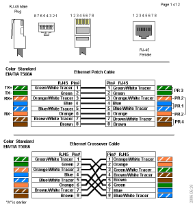
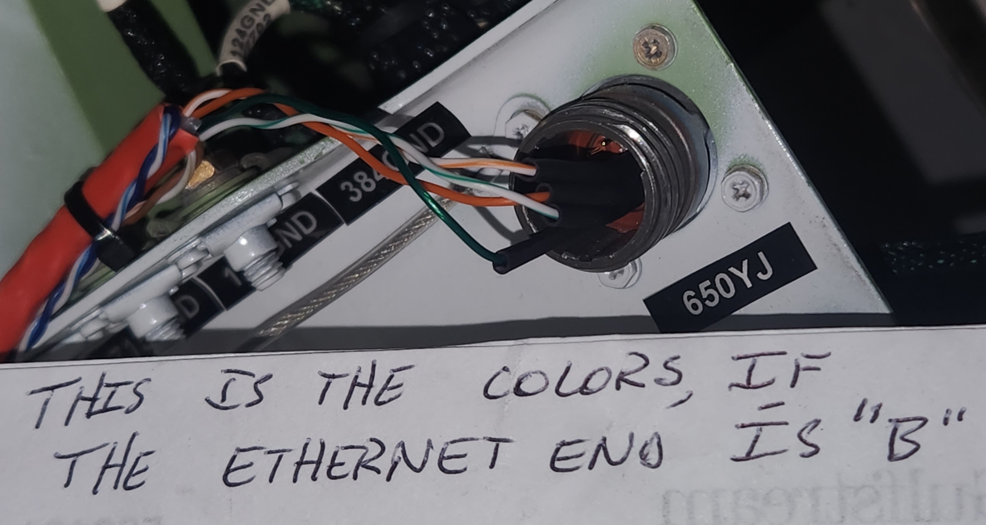
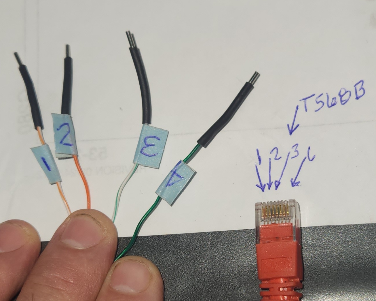
Orn/wht eth 1 goes to round plug 1
Orn eth 2 to round plug 2
Green / wht Eth 3 to round plug 3
Green Eth 6 to round plug 4

Log entries should be brief such that a typical mechanic could understand the scope of work.
Airframe and Powerplant mechanic.
The A AND P mechanic is allowed to supervise any action he is ALLOWED to perform. The log entry MUST include the name of the person who PERFORMED the work, and the name of the SUPERVISING mechanic.
In the real world, this ONLY occurs on the CAMP cards with 2 signature lines.
Sign-off for repair on part91 airplane.
……….has specific wording
Signoff for inspection on part 91 airplane
……….has specific wording
ONLY a 145 REPAIR STATION can build , retain , and reference a WORK ORDER . A MECHANIC therefore must include any support document in EVERY LOG ENTRY. In the real world, mechanics use brief log entries, and seperate “work packages”, or some such.
A few traps for young players:
1. The owner of the aircraft is responsible for the AIRWORTHYNESS of the airplane. Not the mechanic. This responsibility cannot be delegated under part 91.
However, in the real world it IS frequently delegated to the mechanic.
The mechanic ONLY approves the airplane to return to service. The PILOT actually returns it to service.
In the real world, many pilots will not even walk around te airplane.
2. The mechanic is responsible for WHAT HE DOES. He is responsible to SIGN for what he does.
3. If a mechanic is contracted to do an inspection, he is required to sign the inspection AIRWORTHY or UNAIRWORTHY. In the logbook.
You can’t just stop an inspection, and push the airplane out. An unairworthy finding must be accompanied by a letter with a list of discrepancies delivered to the owner……… Not a detailed log entry.
4. Parts must come from somewhere . Form 8130, or yellow tag, or new stock from a vendor with a cofc. Or Vendor Work order number. Or REMOVED SERVICABLE part with the proper declaration…… somewhere. Minor hardware may or may not be an exception to this rule
5. Something must ALLOW a mechanic to put a part on an airplane. AMM IPC reference, PMA with STC AML that lists the airplane model, or STC drawing that lists a PN, or AC43.13-1B standard pratices , or mechanics declaration that it is general practice…..Something.
6. If you are paid to do a repair, do the repair. You are not required, or paid , to fix incidental descrepancies. You are not doing an inspection.
In the real world we try to make everything we touch “right”
7. Pistons track HOURS. Jets track HOURS and CYCLES.
8. A TWELVE MONTH inspection is valid to the last day of the twelfth month. Plus a certain OVERFLY……..sometimes 1 month. A 120 DAYS inspection is due midnight on the 120th day. In the real world, these dates are fungeable based on the part 91 owners proclivities.
9. Batteries and bottles require special date tracking, even more strict. They are tracked even more tightly than the airframe inspection.
10. AD sign-off MUST include AD NUMBER. DATE OF COMPLIANCE, , COMPLIANCE METHOD, RESULT, and NEXT DUE.
11. ENGINE MAINTENANCE entries belong in ENGINE LOG BOOKS. same for airframe. Never the twain shall meet.
12. A part removed, and another part installed is not a REPAIR. It is not DAMAGE. In the real world , this gets so stretched out that DAMAGE HISTORY is difficult to figure out.
13. Do not describe troubleshooting in the log entry. Sometimes,, it makes sense to describe ACCESS.
14. Any discrepancy on a WORK ORDER must be closed. In some way. Othwise, the pilot is at risk of flying the airplane in a CONDITION OF INDETERMINATE AIRWORTHYNESS. Thats on the pilot.
15.
We replaced all 8 connectors.


Luis
Aeropainting
972 757 8980
Pycharm
pycharm-community in the command for the gui
Winxp only
Bring dump card and clean data card. Smaller than 256mb. Formated fat 16. .( FAT)
Pull cb reer d3
Door will not open till power off
Eject card
Insert dump. Leave door open. Push cb Be paitient.
Wait for complete light.
Pull cb
Insert empty data card.
Expect CHECK MDAU nuisance message.
Win xp explorer to copy to compuTer folder
USE MDAU_READOUT 7.0
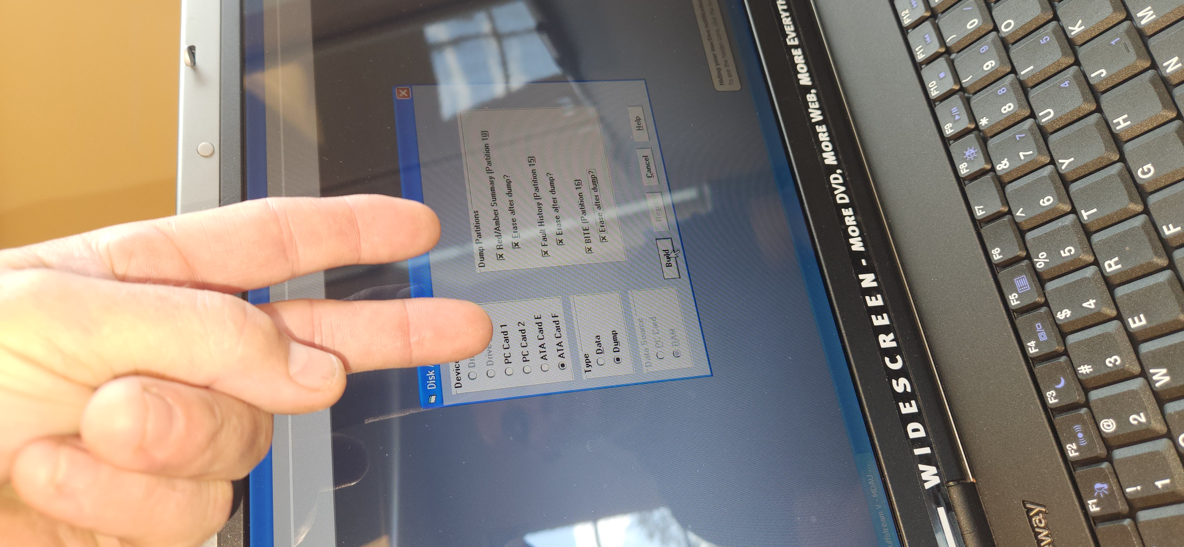
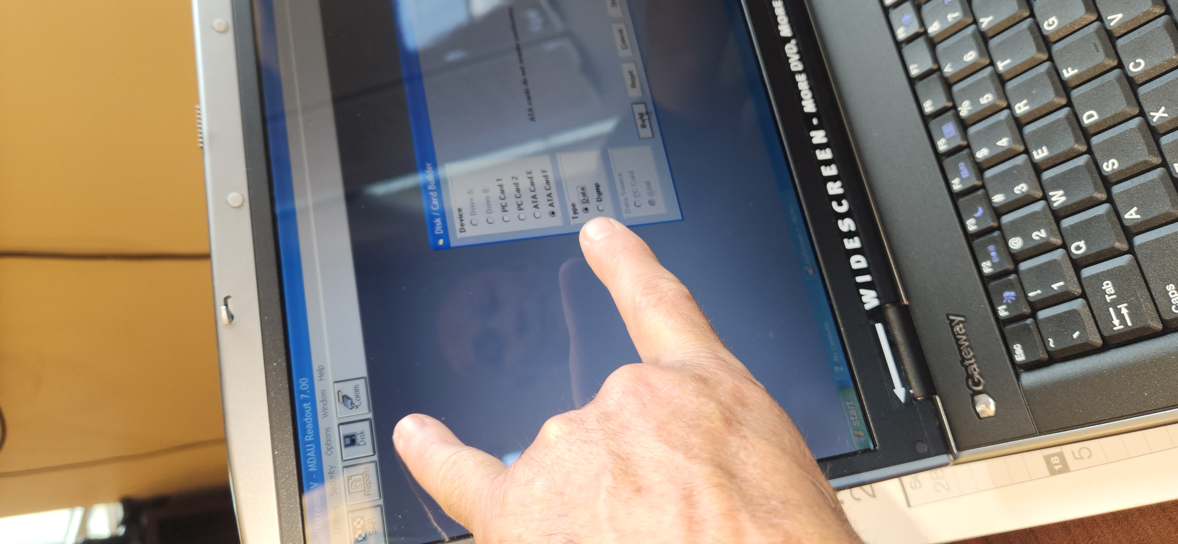
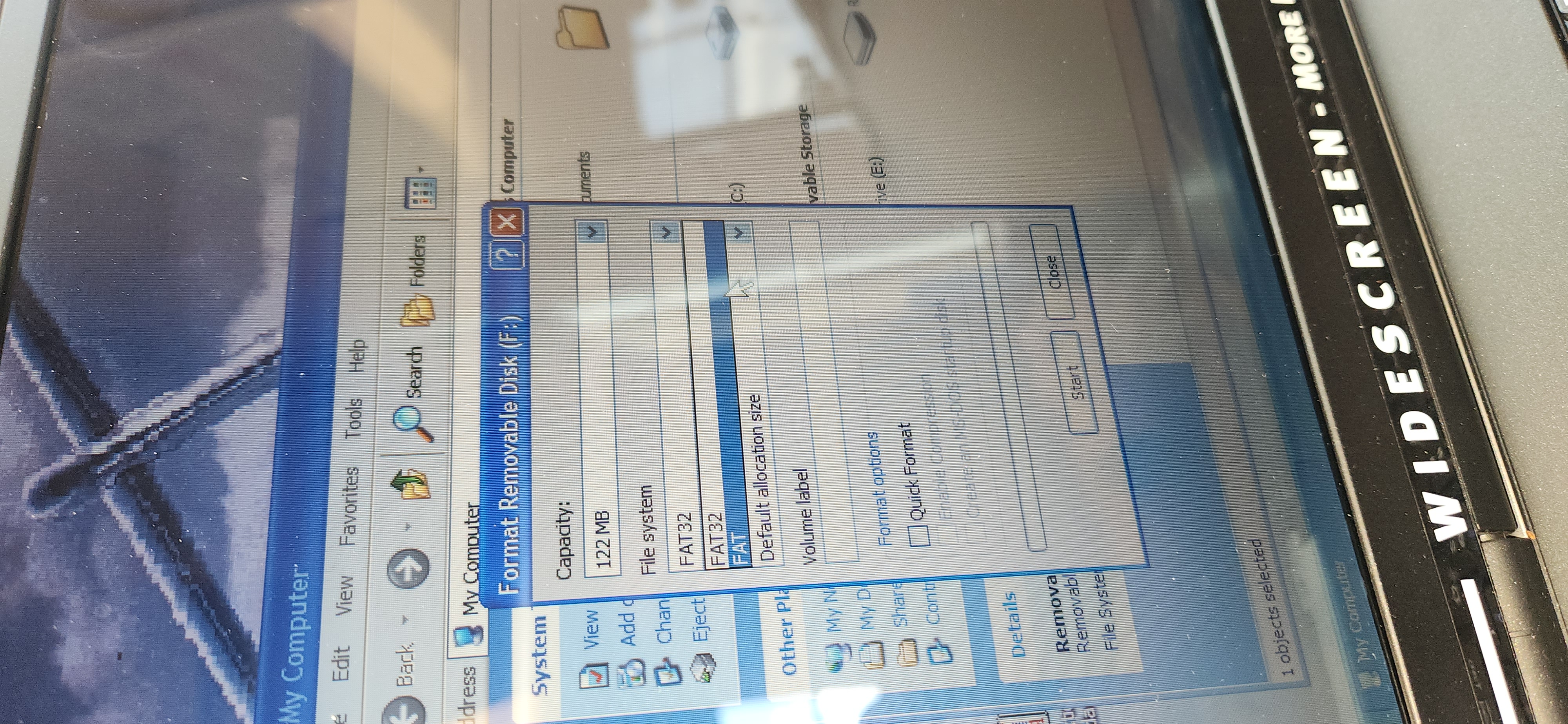
FORMAT one.
Make one dump.