Camera


Camera
1a Existing live stream to You Tube is sufficient for now. We must solve the erratic upload problem now, before we move on. Retry this with internet box tied down and power lead secured.
………………..
http://www.tomshardware.com/answers/id-2234484/lan-cards-internet-lan.html
This is exactly what I did! Figured it out before you posted it though.
NETWORK 1 SETUP (with internet connection)
Router 1 – default settings, DHCP ON
LAN 1 – Static IP 192.168.0.150 (I think you can use auto obtain IP), Default Gateway – 192.168.0.1, w/ DNS
NETWORK 2 SETUP
Router 2 – DHCP OFF
LAN 2 – Static IP 192.168.1.100 ; Default Gateway – Blank ; DNS – Blank
— * It will show as Unidentified Network on your adapter settings window.
I have internet on network 1 while I can file share on network 2 (no internet access) for work. 2 different networks, 1 pc
Why do we have to occasionally hard reset the internet box?
Heavy power switch. Where did the “power Conditioner” go?
Laptop boot on power, sleep on power down
2a – Implement camera feed switch.
2b – laptop to control switching interface
2c – Router from home to mount in 19 in. Rackd. – 2.d current inputs : 1 Sony camera remotely steered, 1 Sony camera fixed at sound booth.
3a. – one remotely controlled camera
3b- Pan/tilt mechanism / controller done, needs tuning.
34c- zoom, focus etcetera.
3d-Evaluate lanc dongle. Buy. Camera XA35.
3e Camera drive. Lanc drive. add joystick or wheel to LANC zoom
4A Why is the fan in the switch so loud?
4b. Key to switch / software /
4c – do we have audio coming in from Sound Booth Channel 8?
4d Get app to work on nexus tablet.
4e. Sound Board private network
SSID X-32
PW @FBCJusti
UP 192.168.0.102
Is ther a way to with the exsisting video on the Lightening outputs
Initial video switcher setup
IP: 192.168.10.240
SUB:255.255.255.0
GATE:192.168.10.1
Initial video converter (red box ) set up
Decimate.
Control duc source , change to HDMI IN
Output 1080i, 59.94.
Control SDI OUT SOURCE. scale if other than I.
Wire run names

http://www.robotshop.com/en/12v-17rpm-200-1-gear-motor-encoder.html?gclid=CjwKEAjw07nJBRDG_tvshefHhWQSJABRcE-Zpd0u3YtILTtxH3PmmDLzu-Tsxf2MBW4cy4B4_5A1fBoCNDrw_wcB
16wvdc motor all electronics
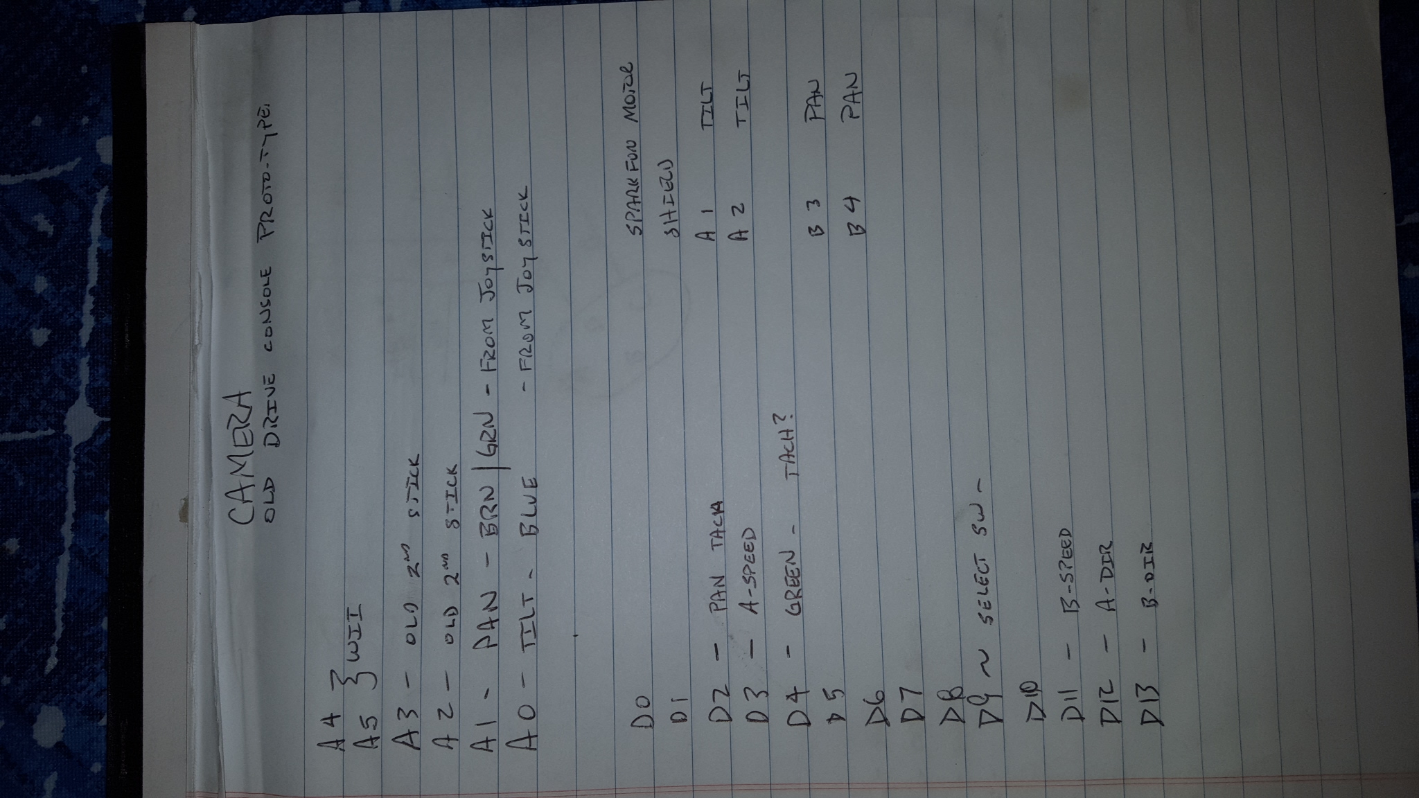
Here is the original BESCOR PanTilt Drive with a WII Nunchuck
Here is the Pan/Tilt with the pan motor tachometer installed
Herre is the initial LANC interface notes
Garage Door Opener Inner Slide Part #: 25605R


1.
2.
3.
4.
5.
6.
7.
8.
9. June 6 2004. 0 to 5.00 memorial day motor cycles. 5.30 Mom with water hose. 9.00 lucia scooter 10.00 Joe lands in j4. June 12 13.26 Lucia rides bike. 21.00 luci shoot footage. 23.30 Florida. 2004. 27.00 grandma. 36.00 lucia skate. with Sam and Kinsey. 49.00 twister 107.00 end.
Uthe Sparkfun motor control board wires up:
Dir A- 12
Speed A – 3
DirB – 13
SpeedB – 11
Here is a wii Nii nunchuck based project
Here ist the demo software for the board:
this is the easy driver from spark fun
this one uses digital smooth
https://github.com/dawsonc/Nunchuck_Turret/blob/master/Nunchuck_Turret.ino
ffqeqe
http://m.aliexpress.com/item/912805423.html?productId=912805423&productSubject=OM400B-joystick&tracelog=wwwdetail2mobilesitedetail

Looks like a decent 3 axis joystick for 40$
http://www.amazon.com/gp/aw/d/B00CS6O4NI/ref=pd_aw_fbt_328_img_2?ie=UTF8&refRID=0W79YEYHETSASKZQN36Z
Hall Effect sensors HAL115C
Installed on the back of a DC motor


Faceplate on the black steering box is 12×7 5-8
Box dimensions

Using a PS2 controller to steer the camers
here is a link to servo drives
http://techmonkeybusiness.com/using-a-playstation-2-controller-with-your-arduino-project.html
dimensions for controller with 4 joysticks
50 mm hole = 1.968 in
63mm = 2.48 in
stroke at the knurl is 1.6

One wire dual direction LAN. Takes 4 identical commands for the rec. to see it as a valid command.
Pulled up to 5V~.
Pulled down =Mark

This drawing is from
http://controlyourcamera.blogspot.com/2011/02/arduino-powered-lanc-remote.html
Use arduino to drive, Plain English:
http://controlyourcamera.blogspot.com/2011/02/arduino-controlled-video-recording-over.html
Example code:
tons of detail:
http://www.boehmel.de/lanc.htm
Vixia HFS200
2.5m
from http://controlyourcamera.blogspot.com/2011/02/arduino-controlled-video-recording-over.html
Nop = 0x0000,
RecordStart = 0x3318,
RecordStop = 0x198C,
IrisIncrement = 0x5528, // Used for IDLE state
IrisDecrement = 0x5328, // Used for IDLE state
IrisRecIncrement = 0x2A94, // Used for RECORD state
IrisRecDecrement = 0x2994, // Used for RECORD state
IrisAutoAdjust = 0xAF28,
FocusShuttleFar = 0xE028, // Used for IDLE state (value mask 0x0F00: 1 3 5 7 9 B D F)
FocusShuttleNear = 0xF028, // Used for IDLE state (value mask 0x0F00: 1 3 5 7 9 B D F)
FocusShuttleRecFar = 0x7094, // Used for RECORD state (value mask 0x0700: 0 1 2 3 4 5 6 7)
FocusShuttleRecNear = 0x7894, // Used for RECORD state (value mask 0x0700: 0 1 2 3 4 5 6 7)
FocusFar = 0x4528, // Used for IDLE state
FocusNear = 0x4728, // Used for IDLE state
FocusRecFar = 0x2394, // Used for RECORD state
FocusRecNear = 0x2294, // Used for RECORD state
these are the few we want to try
| AF | Iris auto |
| 77 | White balance reset (not if white balance is selected via menu) |
| 55 | Iris more open |
55 |
Iris more open |
| 53 | Exposure auto/man. toggle (models of the early 90’s) Iris more close |
| 49 | White balance toggle (only cameras until approx. 1996) |
lanc on a small canon 220 camera uses a 2/32 submini plug RS 274-0298
CANON HFS200 Manual

The command for opening the IRIS is:
Byte 0 – 0010 1000
Byte 1 – 55 (expressed in hexa)
Hi ddenhartog,
You can just need to tick the checkbox “Enable single post download” on the plugin settings. This option is under “Post PDF Export > Post PDF Export Options”.
For other ways to put download button on your post you can check the plugins documentation herehttp://cmdino.com/post-pdf-export/
A !non-embedded! Falcon 50EX below serial number ____ has 9 pin DEEC download ports. Not the same as a F50…Not the same as a 900…not the same as a F50EX with embedded interface. and no, yo cannot just take the upper cowl off and download directly from the DEEC.
A decade ago, Honeywell was able to provide the 9 – pin adapter . for $1800.00 and 6 months lead. Good luck even getting the part number now.
Here is what we worked out after much trial and tribulation! Thanks Marcus!
CAUTION: pin 1 orientation on the RJ12 end is to the left when the tab is held down. You may have a similar !!!! or !!!! reverse cable end. WIre to the pin positions, not the colors.


Okay I have found a third party app that lets me copy everything from Google drive in one easy step – Astro File Manager – it’s a free app on play store, works brilliantly for this as you can select everything in the drive and simply copy it over to your SD Card.
This app will also work with dropbox and other cloud services.
This is a good intro
From:
https://www.physicsforums.com/threads/how-does-120-240-and-440-circuits-work.128535/
Jan 23, 2011 #11 flhampton 1 This might help everyone understand 120/240/440 volt circuits a little bit better. I have a degree in electronic engineering degree from Arizona State University. This doesn’t make me any smarter, but it does allow me to understand how electricity works. They taught us about single phase and three phase transformers in school, but I didn’t really understand things until I started my own consulting business and had to find out how things work for myself. It’s really quite simple. The power company generates 3-phase electricity (3 separate voltage Outputs) from a generator. It is called 3-phase because each output has the same voltage and current capability but it is 120 degrees out of phase with the other two outputs. If you were to look at all three outputs on a scope, you would see three distinct sinusoidal waveforms. Since the generator is operating at 60Hz (60 cycles per second), one complete sinusoidal wave would be output in 1/60th of a second. If you were able to set your scope to 60Hz/division (1/60th of a second), then you would see three separate wave forms per division, each of the three wave forms would be 120 degrees out of phase or 1/3d of a waveform from peak to peak of each wave. It really doesn’t matter what voltage the power company puts out, because they immediately use a 3-phase step up transformer to increase the voltage to 110,000 volts or more. The higher the voltage, the lower the current flow needed for power consumption. Lower current flow means smaller gage wire and less power loss in the lines due to resistance. What is important is that it be at exactly 60Hz, in order to synchronize with all other generators on the transmission grid. Before it gets to you, the home consumer, it is stepped down several times in substation transformers. That transform you see on the pole by your home is stepping down 16KV or 4KV to 120 volts not 240V as most people would believe. There is one primary coil and two secondary coils wrapped around the core of the transformer. The two secondary coils are tied together in the middle, but one of them is wound in the opposite direction. This means that both coils will produce 120 volts but that voltage output between the two of them will always be 180 degrees out of phase. If you measured the output between the two secondary transformers on a scope, you would actually see a 60Hz sinusoidal wave with a crest/peak at +170 volts and trough at -170 volts. That is because the peak voltage of a 60Hz sinusoidal wave is 1.41x the RMS voltage of 120 volts. You are not measuring RMS voltage on the scope you are measuring actual voltage from peak to peak. The center of the two secondary coils is tied to earth ground. It is the same earth ground that you are required to have at your home. If you look inside your main electric service panel, you will usually see two black wires and one white wire coming from the output of your meter. The Black wires come from each side of the two secondary windings of the transformer for your home. The white wire is actually connected to the grounded center wire coming from your transformer. This white wire is called neutral inside your home because it always has a voltage of zero with respect to the two black wires. It is always connected to the ground wire inside your service panel via the common ground/neutral bus. So earth ground and neutral are basically the same wire, but they serve two purposes. Neutral is only used for 120 volt circuits. If you think of electricity in terms of the current flow, then it is the return path for this current. It is returned to the center of the two, oppositely wound, 120 volt, secondary transformers windings. This simply means that 120 volt current flows from one black wire (hot) to neutral. The ground wire is there to protect you in case of a short to the chassis of the equipment in use. If the hot (black wire) inadvertently shorted to a metallic chassis, then it would cause a circuit overload and trip the breaker. If the chassis wasn’t tied to ground then you might get electrocuted when you picked up the equipment. Under the right conditions, your body can conduct electric current from the shorted chassis of that device through you to ground. Your body is not a pure conductor. It has resistance to that flow of current, just like a light bulb has resistance. A light bulb glows and the breaker doesn’t trip because the resistance of the light bulb limits the amount of current flow. Your body can do the same thing. It is possible for you to turn into a light bulb and the circuit breaker will not trip. Basically you fry to a crisp and die. That may seem like overkill, but that is what ground protection is intended for. Your service panel actually has a separate isolated 120volt buss for each of the two hot wires coming in from the transformer. The two busses have several legs. Each leg lies between the legs of the other bus. This means that the voltage between any two legs that are beside each other will always be 240V (RMS) 240 volt current flows between the two legs of the two separate busses. It is not returned to neutral. That is why 240V breakers are usually twice the size of 120Vbreakers. They must connect to two legs, one on each side of the buss. Older 240 volt appliances have a three wire plug. Two of those wires are hot. They come from each branch of the opposing 120V busses. The ground wire is only there for safety purposes should there be a short to the chassis of the appliance. Newer 240 volt appliances have a four wire plug. Two hot wires, one neutral, and one ground. The neutral is there because many 240 volt appliances also use 120 volt sources such as light bulbs, digital displays, etc. You don’t really need the neutral wire because the appliance would still work using ground as a return path for neutral. Remember, neutral and ground are really the same wire. They simply serve two different purposes. So what about 208V systems. You only find 208V wiring in commercial/industrial settings, where three phase wiring is being used. There are two types of 3-phase transformer configuration; delta (as in a triangle), and “Y” (as in the letter). This represents how the different windings of the transformers are connected together. I’m not going to go into transformer theory here. You will have to read about that separately, but I will sum it up. The output voltage across any single phase of a 3-phase delta step-down transformer is 240V or 480V depending on the needs of the end user. 480V would simply be stepped down two 240 as described earlier. Neutral and ground are tied together at the service panel. It only requires three wires to be run to the point of service. Each phase of the transformer can be used for a home. That means that one transformer can provide 120/240 volt service to three different locations. The step-down transformer for your house is set up in a delta configuration because that is what makes it possible to get both 120 and 240 volts out of any one phase or any two wires connected across the transformer. If you needed 3-phase wiring at your home then the power company would have to put in a special transformer just for you at a very high cost, because each of the three legs of their transmission line are undoubtedly already being used in single phase 120/240 delta transformer configurations. Y- Transformer configurations are used in commercial/industrial settings because one transformer can service several clients. That means it is cheaper for the utility company. The output across any two phases of a 3-phase-Y transformer is 208V. One leg of each coil in the transformer is tied together like a “Y”. The voltage across any leg to this common center point is 120V. This is quite convenient, because in the US, every commercial/industrial 3-phase user still needs 120V service. The power company is able to kill two birds with one stone. The end user gets 3-phase, 208V electric service and 120V single phase service for normal appliance use. All 240Volt single phase devices are designed to work using 208V in the US. So if you have a 240V single phase A/C unit or motor, it will work just fine using 208V. It will simply use more current at that voltage. 3-phase motors and A/C units are much cheaper to design. They also require less maintenance and can do more work. They last longer. That’s why commercial/industrial areas use 3-phase electricity. I’m sure most commercial/industrial users would prefer to have 3-phase 240V delta power if they could. But they don’t want to pay for additional transformers to be installed. It would take a long time to recoup the money. This only occurs when extremely large amounts of power are required or when a company purchases a large amount of land, then develops it themselves. The average commercial storefront user is stuck with 208V because of the lower capital equipment cost required when power is initially brought in to an area.
Reference https://www.physicsforums.com/threads/how-does-120-240-and-440-circuits-work.128535/
