I wouldn’t know a back porch from a front porch…..
Old info bout NTSC
Plastic sump drain with age hardened o ring
3 outer buttons, but I cannot remember which 3…… just mash all 4 outer black buttons.
AUTO TUNE requires:
1. No DME HOLD
2. MANUAL TUNE not selected in FMS, or buttons on panel?
3. FMS source selected on HSI.
4. NAV receiver turned on and working..
1. Copilot D-bar dissappear intermitantly when LNAV selected, even though AP steers correctly
2. Copilot ALTSEL mode erratic.
3. FD FAIL when VPATH blue button is illuminated.
Verfied copilot ALTSEL mode would activate, even when FD was not displayed. Reacts to harness being manipulated aft and below FGC 2. drill swarf in harness.
Falcon 50. FZ-500
Light
p/n TAE0428-6
s/n T01174
 A few problems with the Ice Lights
https://youtube.com/shorts/cXWvA59PAoM?si=JrAjI3ahVoWVx39F
Over wing LED emergency over wing lights for
G-II, G-III, G-IV, G-IV-X, G-V, G-V-SP TAE0128-1
scan
LED wing scan insert for G-IV, G-IV-X, G-V and G-V-SP K428-G4-GWS-001 (LH) and K428-G4-GWS-002 (RH)
LED logo light K428-G5-LGL-001 to replace both left and right side logo lights (for G-IV, G-IV-X, G-V and G-V-SP logo lights when installed in underside of stabilizer)
LED wing scan insert for G-IV, G-IV-X, G-V and G-V-SP K428-G4-GWS-001 (LH) and K428-G4-GWS-002 (RH)
LED air stair step lights for G-II, G-III, G-IV, G-IV-X, G-V, G-V-SP TAE0228-1
LED air stair bottom light for G-II, G-III, G-IV, G-IV-X, G-V, G-V-SP TAE0228-2
LED air stair forward light for G-II, G-III, G-IV, G-IV-X, G-V, G-V-SP TAE0228-3
LED emergency over wing lights for G-II, G-III, G-IV, G-IV-X, G-V, G-V-SP TAE0128-1
LED pylon cargo compartment light for G-II, G-III, G-IV, G-IV-X, G-V, G-V-SP TAE0128-3
LED wheel well Light for G-II, G-III, G-IV, G-IV-X, G-V, G-V-SP TAE0128-4
LED emergency under wing lights for G-II, G-III, G-IV, G-IV-X, G-V, G-V-SP TAE0128-5
FAA STC held under ST04177AT
Foreign approvals held for: EASA, ANAC, DGAC, CAAC, FATA and TC
Flap slat test box.
Using the pest points to see the difference between left and right flap
Vest
Lights
Voltmeter
Fuel.
I built complicated test box, shown in this video, by wiring point to point by hand. It is sold. It was time consuming to hand wire difficult circuits.
We are now building S/N 2, using circuit boards. The wires will be very simple, and the complicated interconnect logic will be on 7 circuit boards. I am a novice at designing PCB’s.
We have had some successes that lead us to these steps:
Every item is set out on an EXACT 3/5″ x 3/4″ inch grid. That harmonizes the artwork for the face, with the layout of the PCB. This is a success.
The PCB’s are EXACTLY 5/8 ” below the face. That sets the correct depth for the switch solder tails to attach to the board. here is the drawing we used to arrive at that. 2 boards soldered. That is a success.
The LED’s are resolved by a LED capsule, that pushes through the face, and plugs into a 2 pin female header. These are Dailite 559. We will solder up the first example this week. May be a success.
The PCB’s MUST be removable…… Occasionally……. With some reasonably small amount of effort. that means devises should “front release” and not require extensive labor to de-solder, re-solder.
Here is the heart of the problem:
We need dozens test points, that SOLDER to the 7 PCBs. Pin-Jack, or Banana. The front bezel should unscrew and allow the face to lift off. No such test points exist.
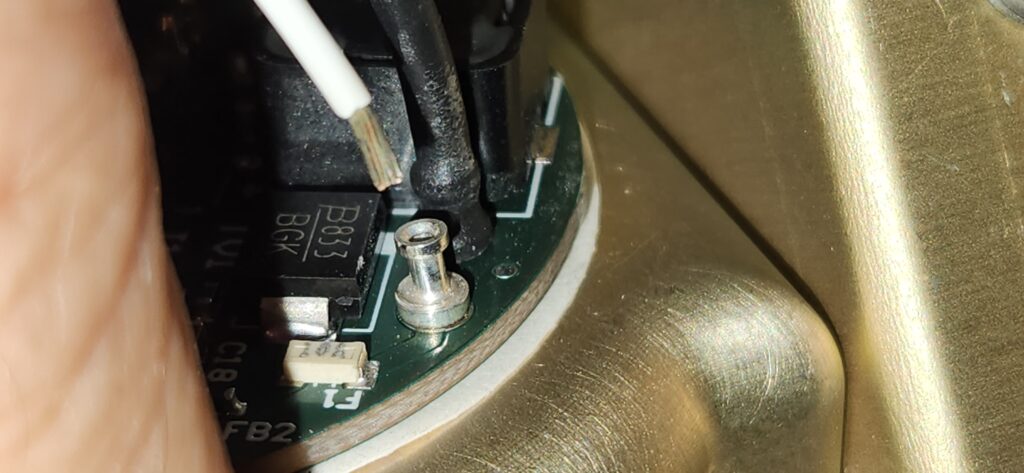
here is the current workaround: A soldered test point that “leans” against a half of a solder pad.
Advantage: for removal, you can desolder and free the tail of the test point toward the large circle.
Disadvantage: every test point must be desoldered to remove the board. This is ~10 test points per board. Next product will have 100’s of test points per board.
2 questions:
1. Using this setup, or similar, is there a method to attach a test point to the pcb, AND secure it to the front panel so that it is removable?
2. Have i missed some vastly easier way to do the entire design?