Category Archives: AircraftTroubleshooting

Problem definition for adding test points to a instrument face

I built  complicated test box, shown in this video, by wiring point to point by hand.  It is sold. It was time consuming to hand wire difficult circuits.

We are now building S/N 2, using circuit boards.  The wires will be very simple, and the complicated interconnect logic will be on  7 circuit boards. I am a novice at designing PCB’s.

We have had some successes that lead us to these steps:

Every item is set out on an EXACT 3/5″ x 3/4″ inch grid.  That harmonizes the artwork for the face, with the layout of the PCB. This is a success.

The PCB’s are EXACTLY 5/8 ”  below the face. That sets the correct depth for the switch solder tails to attach to the board. here is the drawing we used to arrive at that.  2 boards soldered. That is a success.

The LED’s are resolved by a LED capsule, that pushes through the face, and plugs into a 2 pin female header.  These are Dailite 559.  We will solder up the first example this week. May be a success.

The PCB’s MUST be removable……  Occasionally……. With some reasonably small amount of effort.  that means devises should “front release” and not require extensive labor to de-solder, re-solder.


Here is the heart of the problem:

We need dozens test points, that SOLDER to the 7 PCBs. Pin-Jack, or Banana.  The front bezel should unscrew and allow the face to lift off.  No such test points exist.

here is the current workaround:  A soldered test point that “leans” against a half of a solder pad.

populated pc board

Advantage: for removal, you can desolder and free the tail of the test point toward the large circle.

Disadvantage: every test point must be desoldered to remove the board. This is ~10 test points per board.  Next product will have 100’s of test points per board.

2 questions:

1. Using  this setup, or similar, is there a method to attach a test point to the pcb, AND secure it to the front panel so that it is removable?

2. Have i missed some vastly easier way to do the entire design?

Which Flap Slat WDM is effective for which G100?


WDM Effectivity toc-chaptoc-27_chptoc


Astra S/N 080 WDM 2 – flap                     3 – slat
Astra S/N 087 WDM 2 – flap                     4 – slat


Astra S/N 124 WDM 1 – flap                      1- slat
Astra S/N 130 WDM 1 – flap                      1 – slat


27-50-00 figure 2 page 1, mark off jumper center RH

27-80-003 f 3 1  0f 3  label bypass switch wire differences, notes change

27-80 f3  3 of 3 missing wire upper rh on early a/c


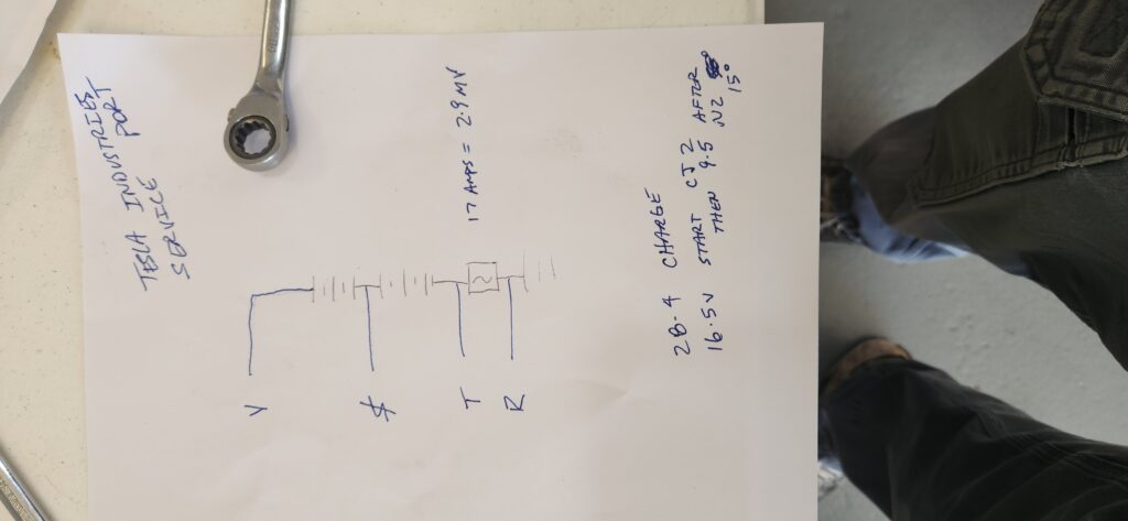
Tesla industry ground power cart


Don’t try this at home.  Exposed 220vac, possible death at every turn.


Now the auction bargin Tesla GPU is operating well with new batteries.


https://youtube.com/shorts/YVwBBMM7kQw?si=GvQ6FLomn2z5tCcr

VIDEO


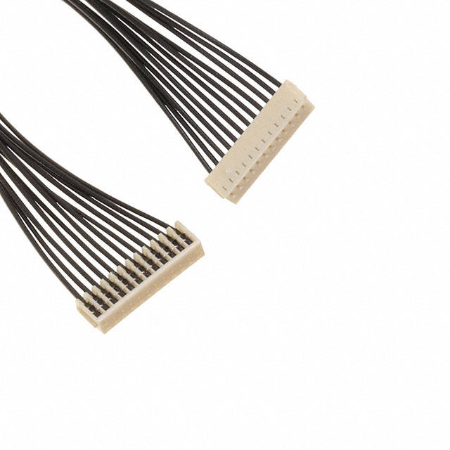
JST-XH 12 position connector

this is close

A12SR12SR30K102A

A12SR12SR30K254A
this looks closer, JST-SH, 12 position with wires:


Falcon 10 pops ANN CB when LAMP TEST button is pushed

Turned out that the Smoke detector in the baggage hatch had a wire broken free, touching the plug shell.


Disconnecting either pilot or copilot ANN COUPLER on the zero  door will clear the fault.   No FD annunciators test in any condition.

R and R 1 pc card in the copilot ann box, now Pilot fms ann test good, copilot dark.  Now AUX bus must be on to get it to pop.  Pilot side still ANN good.


NTE5256A zener in the ann couplers

falcon 10 ann coupler


G-IV LED retrofit


DOM: Duane Moss, 817-368-2846

DER: Verl Herd,  214-763-0262

DAR: CJ Daniel, 817-692-4415

IA: Phillip Ayala, 817-903-9169

Project see-r after-er: Todd Heffley, 817-845-0145

GIV  registration

Wing Tips and Tail Covered by AVEO ENGINEERING, Installation Instructions, EASA STC.  using these instructions.


Supporting Document List

AVE-IS30ANCSAS-02G-IM Here (Smart Strobe)
AVE-MOD-006-MCS  Here
AVE-WP-51G-IM Here (Nebulon Position)
AVE_IM_033 Here  (for AMP disconnect plugs)
AVE-POSW-74G-IM Here (Pegatron Tail Position)
AVE-N09PANSN-IM   Here (Nubion Downwash)

AVE-MOD-006-INS_I05_240529_083542

EASA Minor Change sheet 10061508_CERT_REV_1_20200625-MOD006GIV-GV

page 5 for EASA drawings AVEMOD006DL, issue 02
page 5 for Appliance Authorization.
The following appliances carry an ETSO authorization:
AVEPOSW74G401 ETSOA 21O.10055101
AVEIS30ANCSAS02G ETSOA 21O.10055229
AVEWPR51G401 & AVEWPG51G402 ETSOA 21O.10055070

1 ea. Kit Number: GLF01  – page 8 for wing position lights, left, red
1 ea. Kit Number: GLF02  – page 8 for wing position lights, right, green
1 ea. Kit Number: GLF03 – page 10 for wing  strobe installation
1 ea.  Kit Number : GLF05Page 24 for tail strobe
1 ea. Kit Number:  GLF07 – page 13 for taxi
1 ea. Kit Number:  GLF08 – page 13 for  downwash
1 ea. Kit Number: GLF13 – page 22 for tail pos’n, for G-IV sn 1443


price list AveoEngineeringGroupSTC-GV-USD-v3


2 Ea.  Tip strobes, each tip:
Existing:                                                     Proposed: Aveo
           
Kit Number: GLF03

2 Ea. Wing  Tip Position Lights:
Existing:                                         Proposed:
             
kit Number: GLF01

2 Ea.  tail positions:

Existing:                                                  Proposed:
     

1 Ea.  Tail Strobe:
Existing:                                                    Proposed:


2 Ea.  down-wash lights
Existing:                                              Proposed: Aveo


WDM for existing light installation:
G_IV Anticol Lights
G_IV_ Exterior Lights


Misc order details:
LED Order
Order Detail AveoEngineeringGroupSTC-GV-USD-v3

DAR requested info:


  • Aircraft N Number N305LM
  • Aircraft SN 1443
  • Name of the airport it is located. KDAL
  • Address of the hanger the work is being performed. 8350 Denton Drive , Dallas, Texas 75235, US, Hangar C
  • Name, A&P and Phone Number of the tech doing the work. Todd Heffley, 817-845-0145, AP3281856
  • The primary POC name, phone and email, IF not you.  DOM Duane Moss, 817-863-2846, dmoss@hartgrp.com


Parts Off TAIL:
1 EA, Tail Beacon P/N 30-1994-3 S/N 2049
2 EA, Tail Position P/N 30-2368-1 S/N 0763,

Parts On TAIL:
1 EA, BeaconAVE-IS30ANCSAS-O2G MOD1 S/N 75434-2312-00344


FAA Aand P testing

Federal exams is now

A&P FASTRACK INC

(3)
Aviation training institute in Bethany, Oklahoma ? Open

Thumbnail Image


§ 65.77 Experience requirements.

Each applicant for a mechanic certificate or rating must present either—

(a) An authenticated document from a certificated aviation maintenance technician school in accordance with § 147.21 of this chapter; or

(b) Documentary evidence, satisfactory to the Administrator, of—

(1) At least 18 months of practical experience with the procedures, practices, materials, tools, machine tools, and equipment generally used in constructing, maintaining, or altering airframes or powerplants, appropriate to the rating sought; or

(2) At least 30 months of practical experience concurrently performing the duties appropriate to both the airframe and powerplant ratings.

[Docket FAA-2021-0237, Amdt. 65-63, 87 FR 31415, May 24


-?———–