Here is the Honeywell Checklist Ya – Ya.
Category Archives: Uncategorized
How do you troubleshoot a Falcon 50 ECU?
Here is some Falcon Ya – Ya.
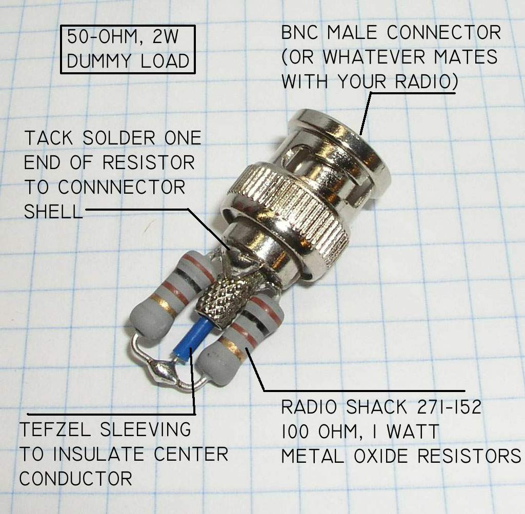
How do you build a dummy load?
here is an example from ‘lectric Bob
How Do you change the battery on a NZ2000?
How Does Aviation Mic Circuit Work?
Short story:
Buy one of these elements and some clip leads and try it.
Long story:
Seems like the basic problem is to get wide voltage swings like a old carbon mike would produce from a electret element as per this explanation
This Mic schematic gives a clue.
This list seems to be the long way around the horn.
Earnest is a real thinker, and here is what he thinks about building a cheap headset
DIY on a couple of lists
+++++++++++++++++++++++++++++++
good deal.
Now
these guys
http://art.simon.tripod.com/stealth.html
are talking about drilling out an airbud and mounting a mic elemnt within.
This allows recording of stereo phonic sound, just the way you ear would hear it.
Sneaking recording devises into concerts and such.
What if you took your idea of a In-The-Ear speaker in one ear, and put a MIC element in the other ear. You should be able to record the human voice, through the ear canal, and do away with ambient wind noise?
Open cockpit application
todd
How do I build up pitot/static hoses?
Freon service hosekit to scavenge the nice end fittings. Each kit offers 6 fittings, so order 2 kits and you will have plenty. They have a nice soft flare seal that is replaceable. Destroy the end crimp. Purchase 3/16 soft rubber service line. Cut to length and have a hose shop crimp new brass sleeves.
You need to end up with at least:
1 Static Hose, 30 Ft with a T, two 10 foot hoses. Long enough to wrap around the fuselage to reach the static ports.
1 pitot hose, 30 Ft with a T, at least a 6 foot on the end. Long enough to reach to each pitot tube.
This does not speak to the airplanes that will need to have the Pilot, AND copilot AND Standby Pitot/Static to be run simultaneously Two more t’s and 4 short hoses required for that.

Freon hoses from :
http://www.r22.org/prod_list.php?sci=30
“CoolGas on the invoice
3/16ths hose and crimp service from:
Kims Hose & Fittings Inc
maps.google.com
2605 White Settlement Road
Fort Worth, TX 76107-1329
(817) 332-8953
++
Here is the the Pitot adapter turned down from a brass fitting. Use normal Vinyl tubing with Worm clamps to slip onto the Pitot tube.
Here is a angled end fitting with dust cap and lanyard made from a Shark Leader

Shark leader and crimper:

Dust caps are just plugs

++++++++++++++++++++++++++++++++++++++++++
Here is the NavAids Canada Adapters:
http://www.navaidsltd.net/Brochure-2006-1.html
Aircraft Ground Support Equipment
Aircraft: Falcon 900
Category: Commuter & Corporate
___________________________________________________________________________________________
Pitot Test Adaptor : P55517M1-3
Pitot Probe Part No. : 50520
Static Test Adaptor : SS44111P-60 – 4
Blanking Adaptor : SS44111PB-60*
Misc Adaptors : 21298L-225-4 / 21298LB-225* Standby Static
Pitot Pre-Test Probe : PT15551
Air Data Accessories Kit : ADAF592-723
Air Data Accessories Kit RVSM : ADAF592-945
Pitot Cover : PC555-17SB
Seal Kit : SK517
Seal and Spacer Kit : SSK517
Lubricating Fluid : LF5050

![]()


Pump outer square seal id 1.372 od 1.61 thick 1.31
Pump lip seal od 1.282. Id .25 shaft.


Why does the Numner 1 Gen Switch trip on a 900
When 6PA cover is off, USE PLASTIC TOOLS. Lots of exposed high power 28VDC.
1.How sure are we that we did not put the bad APU GCU in the number 1 position this spring(During APU Uncommanded Shutdown troubleshooting)? How sure are we that we did not put a bad EXCHANGE GCU in the #1 position.
2.Has 8P1 Been swapped? Tap on 8P1 while Generator is running.
3. Backpin GCU pin P. Watch this voltage while the generator is running. Should be ~27 VDC. fluctuating voltage would be a symptom of the failure.
4. A poor connection at Pin F of the GCU could cause the internal voltage regulation to fail. Check Pin Tension. Ring all the way out to Generator B lead
5.Visually inspect CR17, CR23 4.Remove CI1, Remove 6PA panel plug A and megger the leads on CR17, CR23
6.Remove 6PA panel plug A, and megger the Plug a Pin U to ground. Check the harness side going forward to the red switch.
Previous action:
Late June 2010: Happens on climb out prior to 10,000 feet.
Late June 2010: Performed A Lead megger check again. (New York)
Early June: CI1 and CI3(?) swapped (Switzerland)
HES 1 replaced with new. (Switzerland)
Another Circuit card swapped (Switzerland)
Late may 2010: replaced switch 2PA1 with new. (Bermuda) Mid spring 2010
How do I trouble shoot an XM weather
The Honeywell XM Install Manual A15-7126-001 had instructions that differed.
Gerry Latour
Avionics Repair Manager
glatour@prostaraviation.com
From: Gerald Latour
Sent: Wednesday, January 13, 2010 10:28 AM
To: ‘blowe@longtailaviation.bm’
Subject:
Good Morning Butch,
I received an email from Andy Brown that the XM is still inoperative on VP-BMB. I called XM toady and asked if the account is active yet. They informed me the receiver currently installed is still attached to Honeywell’s demo account. The demo account consists of Aviator Pro level service. They could not tell me when this account will become inactive. Longtail should contact XM and set up an account for receiver ID# CE6NK0CA (800-985-9200).
XM said you should still be able to receive all data associated with Aviator Pro on the demo account. I would suggest the following steps for troubleshooting this issue:
1) Activate the account with XM.
2) Do a system refresh using the ID CE6NK0CA at xmradio.com/refresh just prior to the next flight. The refresh should be requested while the aircraft is outside with a clear view of the southern sky and have power available for up to 45 minutes afterward.
3) Inspect the receiver for a red led with power applied.
4) Check for power and ground at the receiver. (28VDC at pins 18 and 19; GND at pin 37)
5) Check center/shield resistance of the XM coax at the receiver with the antenna connected with a digital meter. It should be around 30 ohms.
If these steps do not yield positive results I would like to connect an EFB to the receiver data connections that the File Servers are currently using to see if we have a File Server issue. Can you provide the Part Numbers of the File Servers?
Thanks,
Gerry Latour
Avionics Repair Manager
glatour@prostaraviation.com
Ph: 603-627-7827 (Ext. 118)
Cell: 603-566-2767
Pro_Star_logo_1035x800
Service Bulletin to cycle the power when you coast-in to the US
XM_Cycle_thePower_D201008000063
Phone Number
This activation will terminate automatically without prior
notice. To avoid unexpected deactivation, customers should contact XM Satellite
Radio Inc. at 1-800-985-9200 to transfer the subscription immediately after
installation.
Please contact
Installation Manual Notes
WX Interface 115.2Kbaud, No parity, 8-bit, 1 stop bit, RS 422
Craig’s troubleshooting in San Antonio on BZZ, June 6 2014:
Installed XM receiver now is D is DB3QX00B. contact with Ana was 1-800-985-9200.
The account number for Longtail 1-4982589656
HeadsUp technology says this about baud rate settings
XMD Baud Rate Dipswitch Settings
The baud rate for the XMD receivers is controlled by dipswitches 7 and 8. These are the switches located adjacent to the bottom connector and are the farthest from the connector. Switch 8 is the outmost.
Both down 125K
7up 8down 115.2 K
Both Up 57.6 K
Paper Flow for Longtail Spring 2010
Deferesd Squawk:
First. Job Card with NRC.
Second: Tech Log Page
Third : Defer Defect
use exact wording.
What Megger and MilliOhm meter should I use?
http://www.tequipment.net/Extech380580.asp MilliOhm Meter (Static Wick Bases, Radome Bonding, ETC.)
http://www.tequipment.net/Fluke1503.html Megger (Static Wicks)
380580-NIST ……380580 with NIST Certificate
380565…………….Test Leads w/Kelvin clips for 380580