Category Archives: F900 Troubleshooting

Holds Falcon 900 specific troubleshooting information

How could Ice accumulate on the inlet screen while ground running the APU on a Falcon 900?

Lou……..

Only a Texan would take a picture of ice!

I ran he apu on f900 087 for 2 hours this morning configuring a satcom.

Light blowing snow……..In Texas!…….

This ice formed inside the inlet.

Is this a known deal?

Looks like if we had restarted the APU  it might have been a bad day at the airport.

___________________________________________________________________

Two more interesting factoids.

The engine shop ran a 900 ex for quite a long time the same morning .  It came in about 45 min after we took the picture.

It had exactly the same ice on the inlet screen. But it was only 1 inch long.

While shutting down the apu, I noticed engine 2 oil temp was 50 deg c.  I had not run engine two at all, and the oat was 15 deg f.

That sounded a little suspicious, so we climbed all over the no.2 engine doing another leak check.

Sure enough there was a crack in the flange of the fgfb72155500a2 venturi pipe.

It was filling the number 2 engine cowl with hot bleed air.  That probably added to the amount of snow that melted off of the cowl and ran down into the inlet.

Bizaar set of circumstances.

F900_Fuselage_-_APU_air_intake_-_Protection_against_fluid_ingestion_during_de-icing_procedure

How do I load the Perf Data Base in a NZ2000

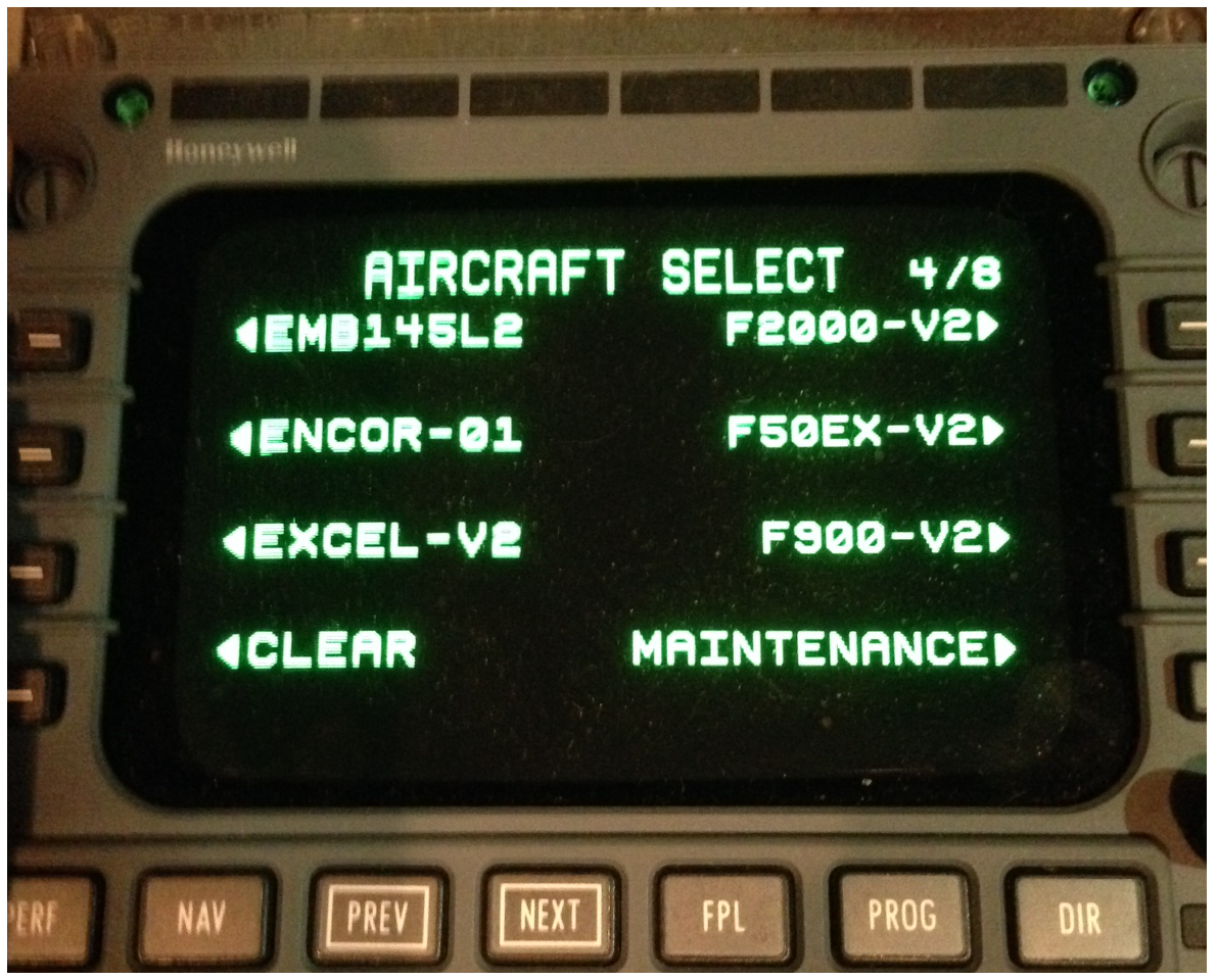
Insert the USB key with the regular Nav Data Base.  The Aircraft Data Base files are on the same disk.
On the “DATA LOAD page, the 2R key should say ‘Aircraft DB”.  … If the stick has the DB on it, and it is plugged in to the data loader correctly.
Choose f900V2 or some such.
Page 6-172 of the pilots guide.
You must load both sides seperatly.
__________________
Some other notes
http://www51.honeywell.com/aero/portal/images/Direct-TO_August2010.pdf
My performance values do not seem to be correct (ceiling altitude splits, cruise alt splits,
ETE’s, Fuel Estimates)
1. Verify that the proper Aircraft Database is in use. You can do this by looking on PERF INIT
page 1, under ACFT TYPE. This should correspond to your specific aircraft.
2. If the ACDB is incorrect (or to clear and reset ACDB performance to the default values) reload
the correct ACDB. The ACDB is available on either floppy disk 1 or 2 or the USB thumb drive
(as appropriate) of your monthly Navigation Database update.
Repeat all Data Load, Tail # and V-Speed Label steps on all CDUs.
3. Verify that SmartPerf Learning is turned
ON
on all FMSs until performance values are as desired.
At that point, turn
OFF
SmartPerf on all FMSs. Leaving SmartPerf
ON
for an extended period can

cause a divergence in the performance data saved in the individual FMSs, causing problems

How do I come to terms with the Primus 2000 “Download and Clear” BrewHaHa

If you get a “Avionics Maint” white message:


You can ignore it.  Or you can go through a 1 YEAR hassle trying to get all of this stuff figured out..


Hart Aviation:

We build a Primus Data Loader, P-2000 Maintenance Access Unit, (Built to Honeywell Drawings). This unit was built for the roughly 19 Falcon 900’s that did not have built in data access ports. (See our web site under the Falcon 900 section near the end of the page) We have one on hand which sells for $4250.00.

F900ex S/N 028 the l42FV and R42FV are under the blank covers in the side consoles.


here is the written instructions:

F900EX Primus 2000 Download & Clear Procedures


MAU Drawing

MAU Drawing


What in the world is this?

com.merx.npoint.servlets-1


1 year

DLC


Old Notes on VQ-BYT

F900EX Avionics Download 2017-05-15


This is the MAU drawing fir Modified F900SN022


How do I make peace with the Printer on BZZ?

Here is the last action when Hugo worked on it:


Hi Todd, below are the steps we took to fix the printer issue.


1.       Wireless printer was configured to connect to some unknown wireless network. So we had to reset the printer when we took it back to the office.

2.       We upgraded the firmware on the printer so that it could support air print. We enabled Bonjour on the printer.

3.       Configured printer with IP address 192.168.1.173 and successfully connected it to the plane’s “VQBZZ Wireless Access” network

4.       Tested printer successfully from windows laptop via wireless and iPad via air print.

Hugo E. Sanchez 

P 210 321 8572
C 210 663 3163
E hsanchez@argogroupus.com

How do I come to terms with Fault Codes in a SPZ-8000 for F900?

Here is the simple break-in to get the codes:


REMEMBER::::::

If you pull the breakers in the air as a matter of troubleshooting, the codes are lost!

If you land and power down airplane, the codes are lost!


If you are using this diagnostic on the ground after powerdown,  YOU ARE WASTING YOUR TIME!  It’s like giving a dog investment advise.  It’s not helpful, and it anoys the dog.


Flight Fault summary must be performed after aircraft lands, before power is turned off.
YD and MTRIM must be dark.
At the copilots left elbow in the engineers Panel.
There is a Bat Handle switch labeled “AFCS TEST” or some such.
Select it up.
The ID802 panels will self test.
Then , When they are finished you should see “01 – FGC TEST?” Do NOT perform the test now.
Instead, push the LAFCS button which in this case acts as a “Previous Screen” button.
A few screens back, you will get to “98 – FLGHT FAULT SUMMARY”
Push “RESET” to get to the flight fault screen.
That should show the codes for the LEFT computer.
Take a picture of that screen.
Now press reset again.
That should show the RAFCS faults.
Take a picture of that screen
+++++++++++++++++++++++++

Here is the Spreadsheet that unwraps the Hex code to plain english…. or as plain english as a Honeywell engineer can make it.


This one runs under Libre Office:

SPZ-8000-Flight-Fault-Summary   .ods


This one runs under excel:

SPZ-8000 Flight Fault Summary


SPZ-8000-Flight-Fault-Summary – this one is from Augusta

I think these spreadsheets were written by Terry Markovich.  Genius that ran Duncan TEB back in the day. Super clever.

here is an example fault code


Plain Text trouble shooting book:


Falcon 900 DFZ TS Guide

How do I come to terms with Arduino-429 interface?


Fast opto SOIC 8 2 CHANEL VO2630-X007T


Steps to develop a cheap ESP32-based ARINC 429 reader using two optocouplers for bit-banged reception + a simple web page for text output.

1. Understand the signal and safety constraints

  • Differential levels (A – B):
    • Logic 1 (HI): ~+6.5 V to +13 V
    • NULL: ~–2.5 V to +2.5 V
    • Logic 0 (LO): ~–6.5 V to –13 V

2. Hardware design (cheap discrete front-end)

  • Series current-limiting resistors (a few mA).
  •  series protection resistors + TVS diodes or clamping for transient robustness.
  • Two optocouplers6N137 / TLP2361 / similar high-speed optos if you target 100 kbps).
  • On the ESP32 side: pull-ups (external 4.7–10 k?)
  • Power the opto output side from the ESP32 3.3 V rail; keep grounds separate (true isolation).

Sketch the circuit, calculate LED current, verify rise/fall times on a scope with a real or simulated ARINC source, and add decoupling. Keep the analog/high-voltage side physically separated from the digital side.

Alternative low-cost approaches (if pure optos prove too slow or awkward): discrete comparators (e.g., LM393 or better) followed by digital isolators, or the op-amp + logic circuits used in some open ESP32 ARINC boards. Stick to two optos if that is the design goal.

3. ESP32 platform and pinout

  • (dual-core is helpful).
  • GPIOs for the opto outputs (e.g., GPIO 18 / 19).
  • Power from USB or a clean 5 V ? 3.3 V regulator.
  • Optional: status LEDs, a small display, or Ethernet if Wi-Fi is unreliable.

4. Software – bit-banged receiver

Use Arduino-ESP32 or ESP-IDF + FreeRTOS.

High-level approach:

  • Configure the two GPIOs as inputs with pull-ups.
  • Use pin-change / edge interrupts (or a high-priority FreeRTOS task + polling) to capture transitions on either line.
  • Measure pulse widths with micros() or a hardware timer.
  • State machine that recognizes:
    – Start of a word (first HI or LO pulse after a long NULL gap).
    – Each bit: first half active (HI = 1, LO = 0), second half NULL.
    – End of word after 32 bits + inter-word gap.
  • Assemble the 32-bit word (label is bits 1–8, usually octal; data, SDI, SSM, parity).
  • Check odd parity (bit 32).
  • Buffer received words (circular queue or FreeRTOS queue) so the web server can read them without blocking the decoder.
  • Optionally auto-detect speed by measuring bit period, or hard-code 12.5 / 100 kbps.
  • Run the decoder on one core; keep Wi-Fi / web server on the other.

Start simple: capture raw HI/LO events and print timings to Serial. Then add word assembly and label filtering.

5. Web interface for simple text output

  • Use the built-in WebServer or better ESPAsyncWebServer (non-blocking).
  • Create an Access-Point mode or join an existing Wi-Fi network.
  • Serve a minimal HTML page (plain text or a simple table) that:
    – Shows the latest words (label in octal, raw hex, decoded fields if you implement a basic BNR/BCD parser).
    – Optionally auto-refreshes via meta-refresh or a tiny JavaScript fetch every second.
  • Optional: WebSocket for live streaming of new words.

6. Development and test sequence

  1. inject known ±5–10 V
  2. Write a minimal interrupt logger that timestamps every edge.
  3. refine the timing state machine until you reliably get 32-bit words with correct parity.
  4. Add the web server and confirm the page updates.
  5. Stress-test with continuous traffic, noise, and both speeds.
  6. Add basic error counters (parity fails, framing errors, gaps too short).

  • Open-source references worth studying: low-cost ESP32 ARINC boards that use op-amps/logic (search “ARINC 429 TX-RX Board ESP32”), RP2040 PIO-based designs, and classic Holt HI-8588 receiver + AVR interrupt examples (the software structure is transferable).

Once the hardware front-end produces clean HI/LO digital signals, the rest is mostly careful timing and a lightweight web UI. Start with low-speed, get solid word capture on the serial console, then add the web page.


================================================

Here is a wonderfull 429 overview

429commentary

airinc_429TheAvionicsHandbook_Cap_2


https://batchpcb.com/pcbs/73951 ia a universal converter project.


The fellows name is AllThumbs on VAF http://www.vansairforce.com/community/showthread.php?t=95229


http://www.vansairforce.com/community/archive/index.php?t-82604.html thread about the SL30 to Dynon HSI


http://www.instructables.com/id/Interfacing-Electronic-Circuits-to-Arduinos/ is a very nice explanation of a 429 to 232 converter

Here is the data from Niel on the frankenverter

FrankenVerterInitialFiles.tar

+++++++++++++++++++++++++++++++++++++++++++++++++++++++++++++

here is a nice blurb on using a parallel port to test AIRINC 429 equipment

testing429WithPC


here is some detail abouthe labels

Arinc429WordList (copy)

Here is the first Distillation of equipment labels

Labels


=============================================

2024 revival project

https://github.com/ncormia/FrankenVerter

https://github.com/ncormia/FrankenVerter/blob/master/a429.h

https://github.com/ncormia/FrankenVerter/blob/master/FrankenVerter.ino


Explanation with scope